Design and specifications are each subject to change without notice. Ask factory for the current technical specifications before purchase and/or use.
Should a safety concern arise regarding this product, please be sure to contact us immediately.
A±0.2
W
( )Reference
φD±0.5
H
B±0.2
(I)
K
(P)
(I)
L
+
‒
0.3 max.
Pressure Relief
(φ10 and larger)
Capacitance (μF)
Negative polarity marking (-)
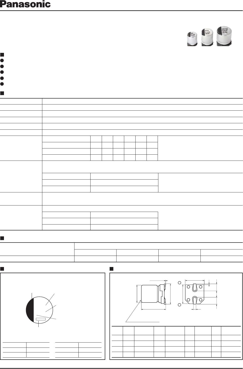
Aluminum Electrolytic Capacitors/FKS
Aluminum Electrolytic Capacitors/FKS
Surface Mount Type
Series:
FKS
Type:
V
High temperature Lead-Free reflow
Specifications
Size
code
-0.20
-0.20
Marking Dimensions in mm (not to scale)
Example:6.3
V.DC /
270μF
Marking color:BLACK
Features
Endurance: 2000 h at 105 ℃
Endurance: 2000 h at 105 ℃
1 size smaller than series FK
1 size smaller than series FK
AEC-Q200 qualified*
-55 ℃ to +105 ℃
6.3 V.DC to 50 V.DC
39 μF to 1800 μF
±20 % (120 Hz/+20 ℃)
l ≦ 0.01 CV or 3 (μA) After 2 minutes (Whichever is greater)
l ≦ 0.01 CV or 3 (μA) After 2 minutes (Whichever is greater)
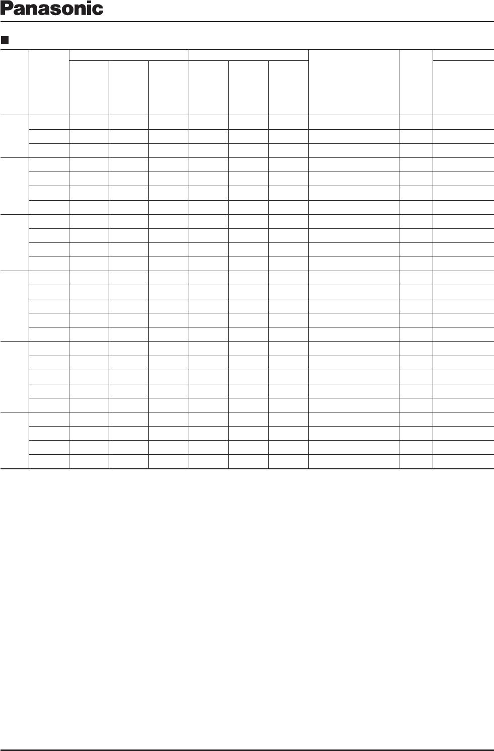
Please see the attached Standard Products list
Please see the attached Standard Products list
(Impedance ratio at 120Hz
(Impedance ratio at 120Hz)
After reflow soldering and then being stabilized at +20 ℃, capacitors shall meet the following limits.
After reflow soldering and then being stabilized at +20 ℃, capacitors shall meet the following limits.
±10 % of initial measured value
±10 % of initial measured value
+0.15
+0.15
Frequency (Hz)
Capacitance (μF)
Frequency correction factor for ripple current
Unit:mm
02 Oct. 2015
Vibration-proof product is available upon request. (φ8 mm and larger)
Vibration-proof product is available upon request. (φ8 mm and larger)
W.V.(V)
Z(-25 ℃)/Z(+20 ℃)
Z(-40 ℃)/Z(+20 ℃)
6.3
10
16
25
35
50
Z(-55 ℃)/Z(+20 ℃)
±30 % of initial measured value
±30 % of initial measured value
39 to 1800
120
0.65
1k
0.85
10k
0.95
100k to
1.00
270
j KS
25 V.DC
35 V.DC
50 V.DC
6.3 V.DC
10 V.DC
16 V.DC
Rated Voltage Mark
D8
6.3
6.3
8.0
10.0
5.8±0.3
7.7±0.3
10.2±0.3
10.2±0.3
6.6
6.6
8.3
10.3
7.8 max.
7.8 max.
10.0 max.
12.0 max.
2.6
2.6
3.4
3.5
0.65±0.1
0.65±0.1
0.90±0.2
0.90±0.2
1.8
1.8
3.1
4.6
0.35
0.35
0.70±0.2
0.70±0.2
A, B
≦ 200 % initial specified value
≦ 200 % initial specified value
≦ initial specified value
≦ initial specified value
≦ initial specified value
≦ initial specified value
≦ initial specified value
≦ initial specified value
RoHS directive compliant
Category Temp. Range
Rated
W.V.
Range
Nominal Cap. Range
Capacitance Tolerance
DC Leakage Current
tan δ
Endurance
Shelf Life
Resistance to
Soldering Heat
Characteristics
at Low Temperature
Capacitance Change
Capacitance Change
tan δ
tan δ
DC Leakage Current
DC Leakage Current
Series identification
Rated voltage mark
Lot number
* This product qualify for AEC-Q200, but it has some deviations.
After applying rated working voltage for 2000 hours at +105℃±2℃ and then being stabilized at +20℃,
After applying rated working voltage for 2000 hours at +105℃±2℃ and then being stabilized at +20℃,
capacitors shall meet the following limits.
capacitors shall meet the following limits.
After storage for 1000 hours at +105 ℃±2 ℃ with no voltage applied and then being stabilized at +20 ℃,
After storage for 1000 hours at +105 ℃±2 ℃ with no voltage applied and then being stabilized at +20 ℃,
capacitors shall meet the limits specified in Endurance. (With voltage treatment)
capacitors shall meet the limits specified in Endurance. (With voltage treatment)