IDT6V31021
4-OUTPUT LOW POWER FANOUT BUFFER FOR PCIE GEN3 AND 10G ETHERNET
IDT®
4-OUTPUT LOW POWER FANOUT BUFFER FOR PCIE GEN3 AND 10G ETHERNET 4
IDT6V31021 REV A 121311
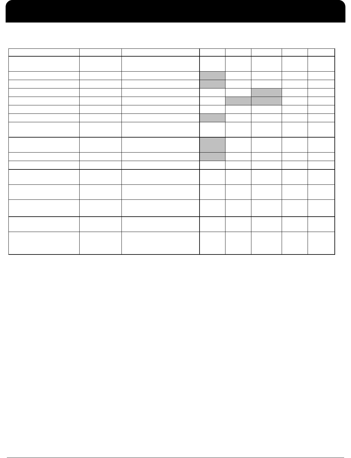
Absolute Maximum Ratings
Stresses above the ratings listed below can cause permanent damage to the IDT6V31021. These ratings, which are
standard values for IDT commercially rated parts, are stress ratings only. Functional operation of the device at these or any
other conditions above those indicated in the operational sections of the specifications is not implied. Exposure to absolute
maximum rating conditions for extended periods can affect product reliability. Electrical parameters are guaranteed only over
the recommended operating temperature range.
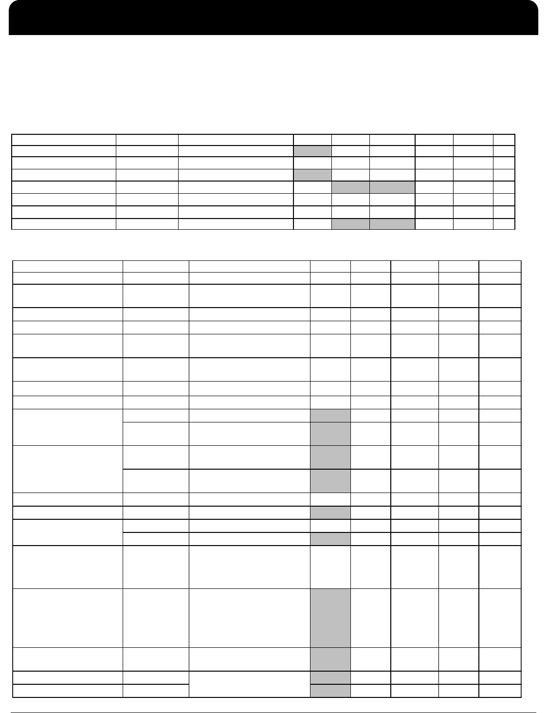
Electrical Characteristics–Input/Supply/Common Output Parameters
PARAMETER SYMBOL CONDITIONS MIN TYP MAX UNITS Notes
Maximum Supply Volta
e VDDA Core Supply Volta
e 4.6 V 1,7
Maximum Supply Voltage VDD_IO
Low-Voltage Differential I/O
0.99 3.8 V 1,7
Maximum Input Voltage
V
IH
3.3V LVCMOS Inputs 4.6 V 1,7,8
Minimum Input Voltage V
IL
Any Input Vss - 0.5 V 1,7
Ambient Operating Temp T
ambIN
Industrial Range -40 85 °C 1
Storage Temperature Ts - -65 150
°
C
1,7
Input ESD protection ESD prot Human Body Model 2000 V 1,7
PARAMETER SYMBOL CONDITIONS MIN TYP MAX UNITS Notes
Supply Voltage VDDA Supply Voltage 3.000 3.3 3.600 V 1
Supply Voltage VDDxxx_IO
Low-Voltage Differential I/O
Supply
0.99 1.05-3.3 3.600 V 1
Input High Voltage V
IHSE
DD
+ 0.3 V 1
Input Low Voltage V
ILSE
SS
- 0.3 0.8 V 1
Differential Input High
Voltage
V
IHDI F
Differential inputs
(single-ended measurement)
600 1.15 V 1
Differential Input Low
Voltage
V
ILDIF
Differential inputs
(single-ended measurement)
V
SS
- 0.3 300 V 1
Input Slew Rate - DIF_IN dv/dt Measured differentially 0.4 8 V/ns 2
Input Leakage Current I
IN
IN
DD ,
IN
DD_3.3V
VDDA supply current 15 20 mA 1
I
DD_IO_133M
VDD_IO supply @ fOP =
133MHz
12 20 mA 1
I
DD_SB_3.3V
VDDA supply current, Input
stopped, OE# pins all high
500 750 uA 1
I
DD_SBIO
VDD_IO supply, Input
stopped, OE# pins all high
100 150 uA 1
Input Frequency F
i
DD
= 3.3 V 15 167 MHz 2
Pin Inductance L
in
IN
Logic Inputs 1.5 5 pF 1
C
OUT
Output pin capacitance 6 pF 1
OE# latency
(at least one OE# is low)
T
OE#LAT
Number of clocks to enable
or disable output from
assertion/deassertion of OE#
1 2 3 periods 1
Clock stabilization time
(from all OE# high to first
OE# low).
T
STAB
Delay from assertion of first
OE# to first clock out
(assumes input clock running
and device in power down
state))
150 ns 1
Tdrive_OE# T
DROE#
Output enable after
OE# de-assertion
10 ns 1
Tfall_OE# T
FALL
RISE
5ns1
Power Down Current
(All OE# pins High)
Fall/rise time of OE# inputs
Input Capacitance
Operating Supply Current