Expand menu
Hello, Sign in
My Account
0
Cart
Home
Products
Sensors
Semiconductors
Passive Components
Connectors
Power
Electromechanical
Optoelectronics
Circuit Protection
Integrated Circuits - ICs
Main Products
Manufacturers
Blog
Services
About OMO
About Us
Contact Us
Check Stock
BSR57,215
P1-P3
P4-P6
P7-P9
P10-P10
BSR56_57_58
All informatio
n provided in thi
s document is
subject to le
gal disclaimers.
© NXP Semiconduc
tors N.V
. 2014. All rights
rese
rved.
Product data sheet
Rev
. 3 — 2
5 June 2014
4 of 10
NXP Semiconductors
BSR56; BSR57; BSR58
N-channel FET
s
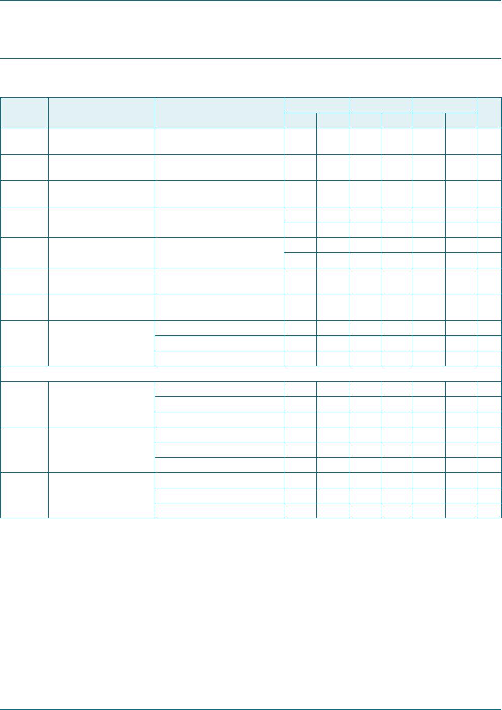
7. Characteristics
T
able 7.
Characteristics
T
amb
= 25
C unless otherwise specified.
Symbol
Parameter
Conditions
BSR56
BSR57
BSR58
Unit
Min
Max
Min
Max
Min
Max
I
GSS
gate-source cut-off
current
V
DS
= 0 V
;
V
GS
=
20 V
-
1.0
-
1.0
-
1.0
nA
I
DSX
drain cut-off current
V
DS
= 15 V
;
V
GS
=
10 V
-
1.0
-
1.0
-
1.0
nA
V
(BR)GSS
gate-source breakdo
wn
voltage
I
G
=
1
A;
V
DS
= 0 V
->
4
0->
4
0->
4
0
V
V
GSoff
gate-source cut-off
voltage
V
DS
=1
5V
;
I
D
= 0.5 nA
>4
-
>2
-
>0.8
-
V
<10
-
<6
-
<4
-
V
I
D
drain current
V
DS
=1
5V
;
V
GS
= 0 V
-
>50
-
>20
-
>8
mA
---
<
1
0
0
-
<
8
0
m
A
C
rs
feedback capacit
ance
V
DS
=0
V
;
V
GS
=
10 V
;
f = 1 MHz
-<
5-<
5-<
5
p
F
R
DSon
drain-source on-state
resistance
V
GS
=0V
;
I
D
=0A
;
f = 1 kHz
-<
2
5-<
4
0-<
6
0
V
DSon
drain-source on-state
voltage
V
GS
=0V
;
I
D
= 20 mA
-
<750
-
-
-
-
mV
V
GS
=0V
;
I
D
=
1
0
m
A
---
<
5
0
0
--
m
V
V
GS
=0V
;
I
D
=
5
m
A
-----
<
4
0
0
m
V
Switching times
(V
DD
= 10 V
; V
GS
= 0 V)
t
d
delay time
I
D
= 20 mA; V
GSM
= 10 V
-
<6
-
-
-
-
ns
I
D
= 10 mA; V
GSM
=
6
V
---
<
6
--
n
s
I
D
= 5 mA; V
GSM
= 4 V
-
-
-
-
-
<10
ns
t
r
rise time
I
D
= 20 mA; V
GSM
= 10 V
-
<3
-
-
-
-
ns
I
D
= 10 mA; V
GSM
=
6
V
---
<
4
--
n
s
I
D
= 5 mA; V
GSM
= 4 V
-
-
-
-
-
<10
ns
t
off
turn-off time
I
D
= 20 mA; V
GSM
=
1
0
V
-
<
2
5
----
n
s
I
D
= 10 mA; V
GSM
= 6 V
-
-
-
<50
-
-
ns
I
D
= 5 mA; V
GSM
= 4 V
-
-
-
-
-
<100
ns
BSR56_57_58
All informatio
n provided in thi
s document is
subject to le
gal disclaimers.
© NXP Semiconduc
tors N.V
. 2014. All rights
rese
rved.
Product data sheet
Rev
. 3 — 2
5 June 2014
5 of 10
NXP Semiconductors
BSR56; BSR57; BSR58
N-channel FET
s
Fig 2.
Switching times wa
veforms
(1)
BSR56; R = 464
(2)
BSR57; R = 953
(3)
BSR58; R = 1910
Fig 3.
T
est circuit
T
able 8.
T
est data
Ty
p
e
Pulse gener
ator
Oscillos
cope
t
r
, t
f
Z
o
C
i
t
r
R
i
BSR56
0.02
1 ns
50
2.5 pF
0.75 ns
1 M
BSR57
0.02
1 ns
50
2.5 pF
0.75 ns
1 M
BSR58
0.02
1 ns
50
2.5 pF
0.75 ns
1 M
aaa-013765
t
r
t
d
0
V
GSM
V
o
V
i
10%
90%
200 ns
t
off
aaa-013764
R
TUT
50 Ω
V
i
V
o
V
DD
BSR56_57_58
All informatio
n provided in thi
s document is
subject to le
gal disclaimers.
© NXP Semiconduc
tors N.V
. 2014. All rights
rese
rved.
Product data sheet
Rev
. 3 — 2
5 June 2014
6 of 10
NXP Semiconductors
BSR56; BSR57; BSR58
N-channel FET
s
8. Package
outline
Fig 4.
Pac
kage outline SOT2
3 (TO-236AB)
References
Outline
version
European
projection
Issue date
IEC
JEDEC
JEITA
SOT023
TO-236AB
sot023_po
06-03-16
14-06-19
Plastic surface-mounted package; 3 leads
SOT023
b
p
D
A
A
1
L
p
Q
H
E
E
0
1
2 mm
scale
c
12
3
B
wB
e
e
1
vA
A
X
Unit
mm
max
nom
min
1.1
0.1
0.15
3.0
1.4
0.2
A
Dimensions (mm are the original dimensions)
A
1
b
p
0.48
cD
Ee
e
1
0.95
H
E
L
p
Qvw
0.1
1.9
2.1
0.15
0.9
0.09
2.8
1.2
0.38
2.5
0.45
0.45
0.55
detail X
P1-P3
P4-P6
P7-P9
P10-P10
BSR57,215
Mfr. #:
Buy BSR57,215
Manufacturer:
NXP Semiconductors
Description:
RF JFET Transistors TAPE7 FET-RFSS
Lifecycle:
New from this manufacturer.
Delivery:
DHL
FedEx
Ups
TNT
EMS
Payment:
T/T
Paypal
Visa
MoneyGram
Western
Union
Products related to this Datasheet
BSR58,215
BSR57,215
BSR56,215