7
For more information www.linear.com/LTC2631
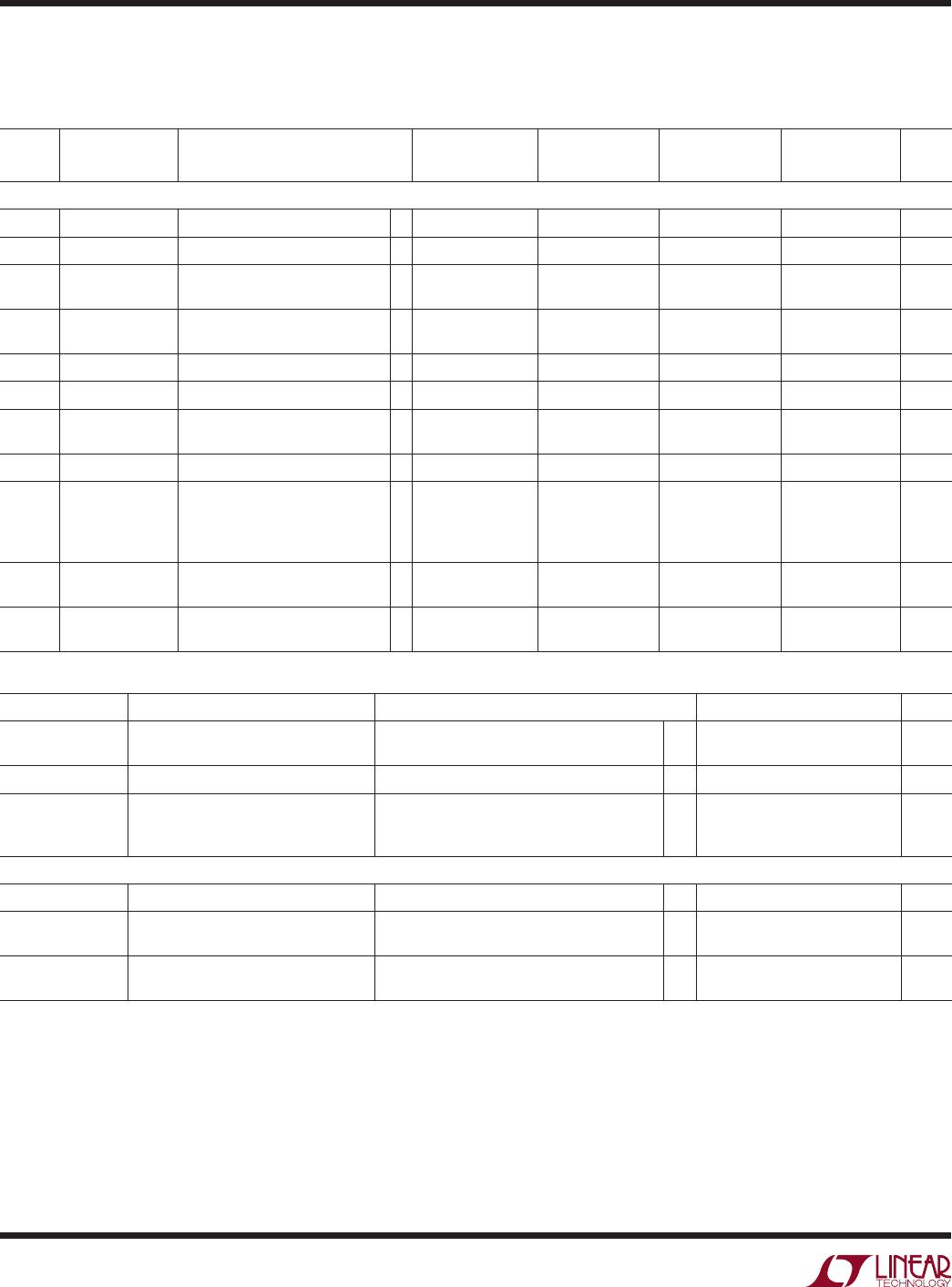
electrical characteristics
The l denotes the specifications which apply over the full operating
temperature range, otherwise specifications are at T
A
= 25°C. V
CC
= 2.7V to 5.5V, V
OUT
unloaded unless otherwise specified.
LTC2631-LM12/-LM10/-LM8/-LZ12/-LZ10/-LZ8, LTC2631A-LM12/-LZ12 (V
FS
= 2.5V)
SYMBOL PARAMETER CONDITIONS MIN TYP MAX UNITS
AC Performance
t
S
Settling Time V
CC
= 3V (Note 9)
±0.39% (±1LSB at 8-Bits)
±0.098% (±1LSB at 10-Bits)
±0.024% (±1LSB at 12-Bits)
3.2
3.8
4.1
µs
µs
µs
Voltage-Output Slew Rate 1 V/µs
Capacitance Load Driving 500 pF
Glitch Impulse At Mid-Scale Transition 2.1 nV•s
Multiplying Bandwidth External Reference 300 kHz
e
n
Output Voltage Noise Density At f = 1kHz, External Reference
At f = 10kHz, External Reference
At f = 1kHz, Internal Reference
At f = 10kHz, Internal Reference
140
130
160
150
nV√Hz
nV√
Hz
nV√Hz
nV√Hz
Output Voltage Noise 0.1Hz to 10Hz, External Reference
0.1Hz to 10Hz, Internal Reference
0.1Hz to 200kHz, External Reference
0.1Hz to 200kHz, Internal Reference,
C
REF
= 0.33µF
20
20
650
670
µV
P-P
µV
P-P
µV
P-P
µV
P-P
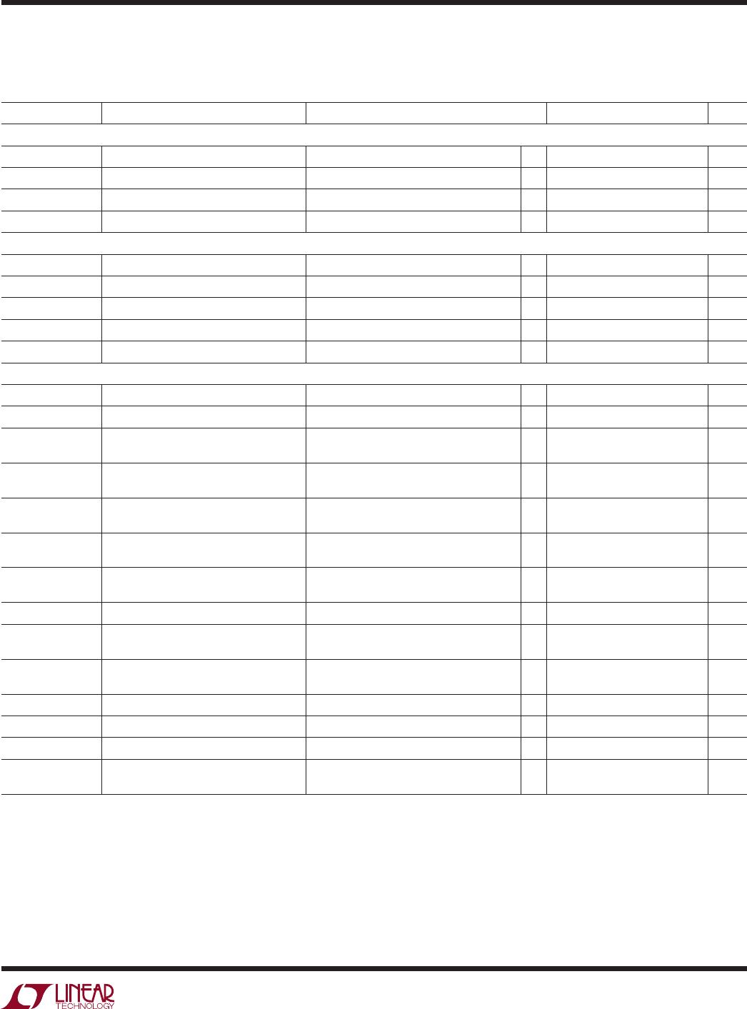
timing characteristics
The l denotes the specifications which apply over the full operating temperature
range, otherwise specifications are at T
A
= 25°C. V
CC
= 2.7V to 5.5V. (See Figure 1) (Note 13).
LTC2631-LM12/-LM10/-LM8/-LZ12/-LZ10/-LZ8, LTC2631A-LM12/-LZ12 (V
FS
= 2.5V)
SYMBOL PARAMETER CONDITIONS MIN TYP MAX UNITS
f
SCL
SCL Clock Frequency
l
0 400 kHz
t
HD(STA)
Hold Time (Repeated) Start Condition
l
0.6 µs
t
LOW
Low Period of the SCL Clock Pin
l
1.3 µs
t
HIGH
High Period of the SCL Clock Pin
l
0.6 µs
t
SU(STA)
Set-Up Time for a Repeated Start Condition
l
0.6 µs
t
HD(DAT)
Data Hold Time
l
0 0.9 µs
t
SU(DAT)
Data Set-Up Time
l
100 ns
t
r
Rise Time of Both SDA and SCL Signals (Note 12)
l
20 + 0.1C
B
300 ns
t
f
Fall Time of Both SDA and SCL Signals (Note 12)
l
20 + 0.1C
B
300 ns
t
SU(STO)
Set-Up Time for Stop Condition
l
0.6 µs
t
BUF
Bus Free Time Between a Stop and Start Condition
l
1.3 µs