FC0402E1000BBT1

FC
www.vishay.com
Vishay Dale Thin Film
Revision: 25-Apr-17
1
Document Number: 60093
For technical questions, contact: thinfilm@vishay.com
THIS DOCUMENT IS SUBJECT TO CHANGE WITHOUT NOTICE. THE PRODUCTS DESCRIBED HEREIN AND THIS DOCUMENT
ARE SUBJECT TO SPECIFIC DISCLAIMERS, SET FORTH AT www.vishay.com/doc?91000
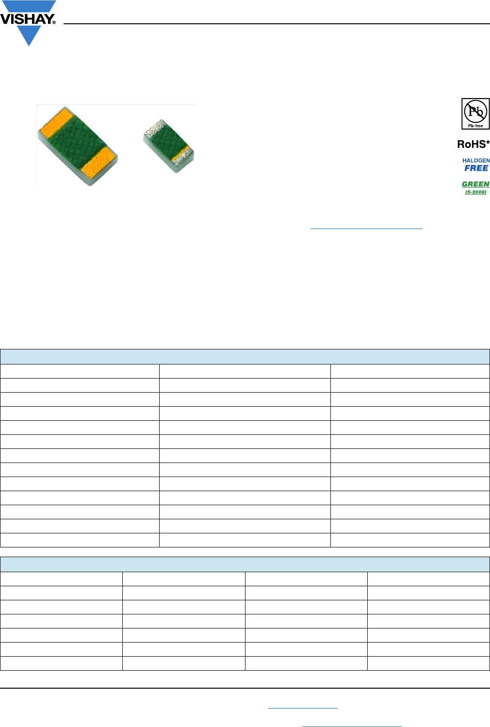
High Frequency (up to 40 GHz) Resistor,
Thin Film Surface Mount Chip
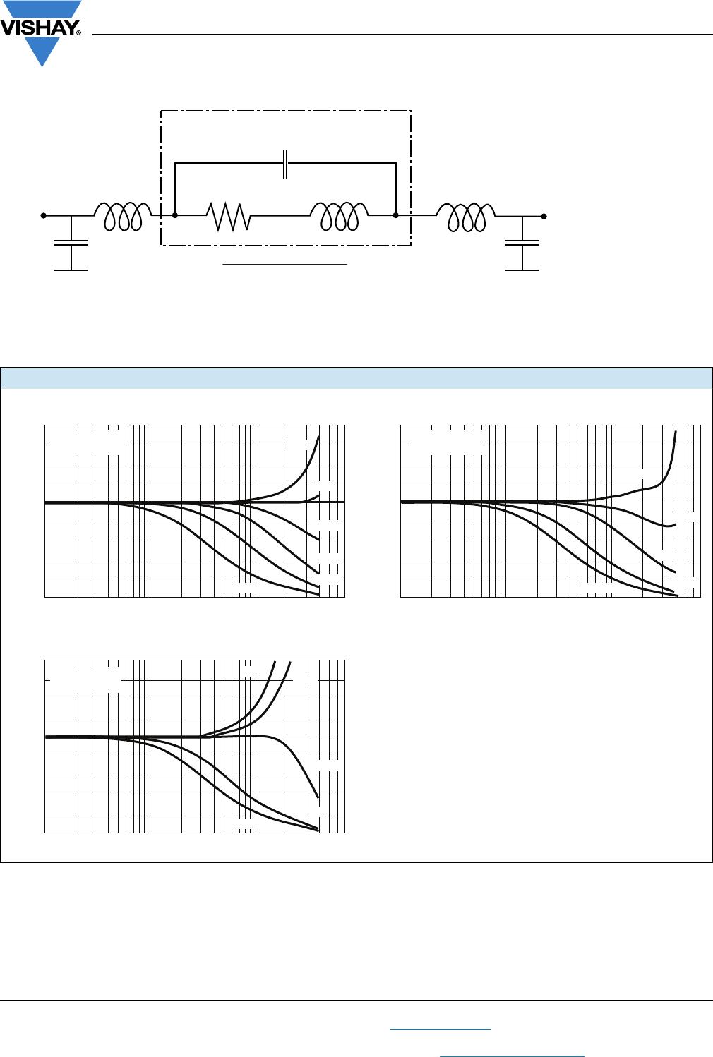
FC series chip resistors are designed with low internal
reactance. They function as almost pure resistors on a very
high range of frequencies. The specialized laser edge
trimming allows for precision tolerances to 0.1 %.
FEATURES
Small standard size 0402 case size
Edge trimmed block resistors
High purity alumina substrate
Ohmic range (10 to 1000 )
Small internal reactance (< 10 m)
Low TCR (down to ± 25 ppm/°C)
Epoxy bondable termination available
Material categorization: for definitions of compliance
please see www.vishay.com/doc?99912
Note
*
This datasheet provides information about parts that are
RoHS-compliant and / or parts that are non RoHS-compliant. For
example, parts with lead (Pb) terminations are not RoHS-compliant.
Please see the information / tables in this datasheet for details
APPLICATIONS
Low noise amplifiers
Attenuation
Line termination
Available
Available
Available
Available
STANDARD ELECTRICAL SPECIFICATIONS
TEST SPECIFICATIONS CONDITIONS
Material Passivated nichrome -
Resistance Range 10 to 1000 Case size dependent
TCR: Absolute ± 25 ppm/°C to ± 100 ppm/°C -55 °C to +125 °C
Tolerance: Absolute ± 0.1 % to ± 5.0 % +25 °C
Stability: Absolute R ± 0.02 % 2000 h at 70 °C
Stability: Ratio --
Voltage Coefficient 0.1 ppm/V -
Working Voltage 30 V to 75 V -
Operating Temperature Range -55 °C to +155 °C -
Storage Temperature Range -55 °C to +155 °C -
Noise < -35 dB -
Shelf Life Stability: Absolute R ± 0.01 % 1 year at +25 °C
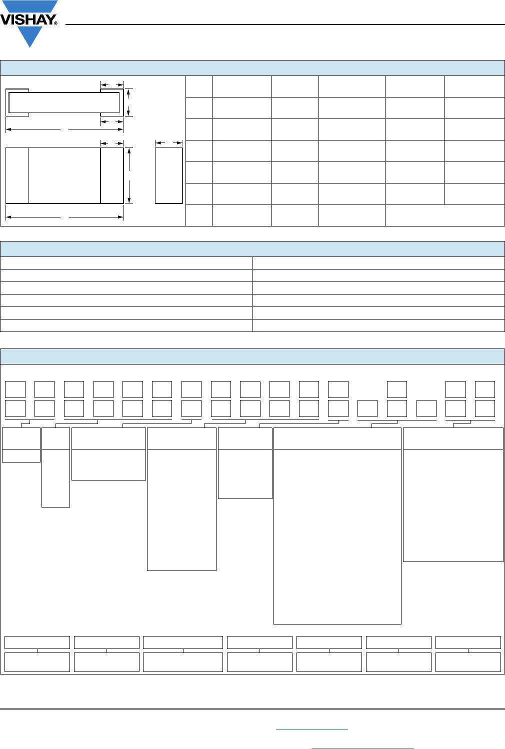
COMPONENT RATINGS
CASE SIZE POWER RATING (mW) WORKING VOLTAGE (V) RESISTANCE RANGE ()
0402 50 30 10 to 1000
0505 125 37 20 to 1000
0603 125 50 10 to 1000
0805 200 50 10 to 1000
1005 250 75 10 to 1000
1206 330 75 10 to 1000
FC
www.vishay.com
Vishay Dale Thin Film
Revision: 25-Apr-17
2
Document Number: 60093
For technical questions, contact: thinfilm@vishay.com
THIS DOCUMENT IS SUBJECT TO CHANGE WITHOUT NOTICE. THE PRODUCTS DESCRIBED HEREIN AND THIS DOCUMENT
ARE SUBJECT TO SPECIFIC DISCLAIMERS, SET FORTH AT www.vishay.com/doc?91000
Note
(1)
Preferred packaging code
DIMENSIONS in inches (millimeters)
CASE
SIZE
LENGTH
WIDTH
W (± 0.005)
THICKNESS
TOP PAD
D (± 0.005)
BOTTOM PAD
E (± 0.005)
0402
0.042 ± 0.008
(1.067 ± 0.203)
0.022
(0.559)
0.015 to 0.0015
(0.381 to 0.0381)
0.010
(0.254)
0.010
(0.254)
0505
0.055 ± 0.006
(1.397 ± 0.152)
0.050
(1.270)
0.015 to 0.0015
(0.381 to 0.0381)
0.010
(0.254)
0.015
(0.381)
0603
0.064 ± 0.006
(1.626 ± 0.152)
0.032
(0.813)
0.015 to 0.0015
(0.381 to 0.0381)
0.012
(0.305)
0.015
(0.381)
0805
0.080 ± 0.006
(2.032 ± 0.152)
0.050
(1.270)
0.015 to 0.0015
(0.381 to 0.0381)
0.016 ± 0.008
(0.406 ± 0.203)
0.015
(0.381)
1005
0.105 ± 0.008
(2.667 ± 0.203)
0.050
(1.270)
0.015 to 0.0015
(0.381 to 0.0381)
0.015
(0.381)
0.015
(0.381)
1206
0.126 ± 0.008
(3.200 ± 0.203)
0.063
(1.600)
0.015 to 0.0015
(0.381 to 0.0381)
0.020 + 0.005/- 0.010
(0.508 + 0.127/- 0.254)
MECHANICAL SPECIFICATIONS
Resistive Element Passivated nichrome
Substrate Material Alumina
Terminations Pre-soldered or gold
Lead (Pb)-free Option 96.5 % Sn, 3.0 % Ag, 0.5 % Cu
Tin/Lead Option Sn63
Lead (Pb)-free Finish and Tin / Lead Hot solder dip
GLOBAL PART NUMBER INFORMATION
New Global Part Numbering: FC1206E1001BBTS
GLOBAL
MODEL
CASE
SIZE
TCR
CHARACTERISTIC
RESISTANCE TOLERANCE
TERMINATION
(1, 2 or 3 digits)
PACKAGING
FC 0402
0505
0603
0805
1005
1206
E
= 25 ppm/°C
H
= 50 ppm/°C
K
= 100 ppm/°C
The first 3 digits
are significant
figures and the last
digit specifies the
number of zeros to
follow. “R”
designates the
decimal point.
Example:
10R0 = 10
1000 = 100
1001 = 1 k
B
= 0.1 %
D
= 0.5 %
F
= 1 %
G
= 2 %
J
= 5 %
T
= Top sided Au (gold) term
Au over Ni epoxy bondable
RoHS-compliant - e4
B
= Wraparound Sn/Pb solder
63 % Sn/37 % Pb with nickel
barrier
G
= Wraparound Au over Ni (gold)
termination epoxy bondable
RoHS-compliant - e4
TB
= Top sided Sn/Pb solder
63 % Sn/37 % Pb with nickel
barrier
TBS
= Top sided lead (Pb)-free
solder with nickel barrier
RoHS-compliant - e1
S
= Wraparound
lead (Pb)-free solder
96.5 % Sn/3.0 % Ag/0.5 %Cu
RoHS-compliant - e1
BS
= BULK
100 min., 1 mult
WS
= WAFFLE
100 min., 1 mult
TAPE AND REEL
T0
= 100 min., 100 mult
T1
= 1000 min., 1000 mult
(1)
T3
= 300 min., 300 mult
T5
= 500 min., 500 mult
TF
= Full reel
TS
= 100 min., 1 mult
Historical Part Number example: FC1206E1001BBT (for reference purposes only)
FC 1206 E 1001 B B T
SERIES CASE SIZE
TCR
CHARACTERISTIC
RESISTANCE TOLERANCE TERMINATION PACKAGING
D
L
E
T
W
L
DT
206K 00011FC BTB STS
206E 00111FC BBT S
FC
www.vishay.com
Vishay Dale Thin Film
Revision: 25-Apr-17
3
Document Number: 60093
For technical questions, contact: thinfilm@vishay.com
THIS DOCUMENT IS SUBJECT TO CHANGE WITHOUT NOTICE. THE PRODUCTS DESCRIBED HEREIN AND THIS DOCUMENT
ARE SUBJECT TO SPECIFIC DISCLAIMERS, SET FORTH AT www.vishay.com/doc?91000
TYPICAL HIGH FREQUENCY PERFORMANCE ELECTRICAL MODEL AND TESTING
The lumped circuit above was used to model the data at the bonding pad-resistor reference plane. High frequency testing was
performed by Modelithics, Inc. on parts mounted to quartz test boards. Quartz test boards were chosen to minimize the
contribution of the board effects at high frequencies.
INTERNAL IMPEDANCE
Lumped Equivalent Circuit
Reference plane is at the resistor-bonding pad interface.
C:
L :
R:
L
C
: External connection inductance
C
g
: External capacitance to ground
C
g
C
g
L
C
RL
C
L
C
Resistance
Internal shunt capacitance
Internal inductance
0402 Wraparound
1.8
1.6
1.4
1.2
1.0
0.8
0.6
0.4
0.2
0.0
Frequency (GHz)
0402 Flip chip
75 Ω
100 Ω
250 Ω
500 Ω
50 Ω
1.8
1.6
1.4
1.2
1.0
0.8
0.6
0.4
0.2
0.0
Frequency (GHz)
0603 Flip chip
1.8
1.6
1.4
1.2
1.0
0.8
0.6
0.4
0.2
0.0
0.1 1 10
Frequency (GHz)
0.1 1 10
0.1 1 10
C = 0.0262 pF
L = 0.00189 nH
C = 0.0403 pF
L = 0.0267 nH
C = 0.0392 pF
L = 0.1209 nH
|Zin|/R|Zin|/R
|Zin|/R
1000 Ω
100 Ω
250 Ω
500 Ω
50 Ω
1000 Ω
75 Ω
100 Ω
500 Ω
50 Ω
1000 Ω

FC0402E1000BBT1

Mfr. #:
Manufacturer:
Vishay
Description:
High Frequency/RF Resistors 100ohms 0.1% 25ppm
Lifecycle:
New from this manufacturer.
Delivery:
DHL FedEx Ups TNT EMS
Payment:
T/T Paypal Visa MoneyGram Western Union