VKP Series
www.vishay.com
Vishay Draloric
Revision: 22-Jul-13
1
Document Number: 22205
For technical questions, contact: slcap@vishay.com
THIS DOCUMENT IS SUBJECT TO CHANGE WITHOUT NOTICE. THE PRODUCTS DESCRIBED HEREIN AND THIS DOCUMENT
ARE SUBJECT TO SPECIFIC DISCLAIMERS, SET FORTH AT www.vishay.com/doc?91000
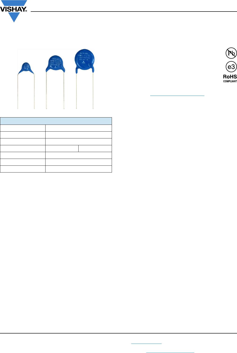
AC Line Rated Ceramic Disc Capacitors
Class X1, 760 V
AC
, Class Y1, 500 V
AC
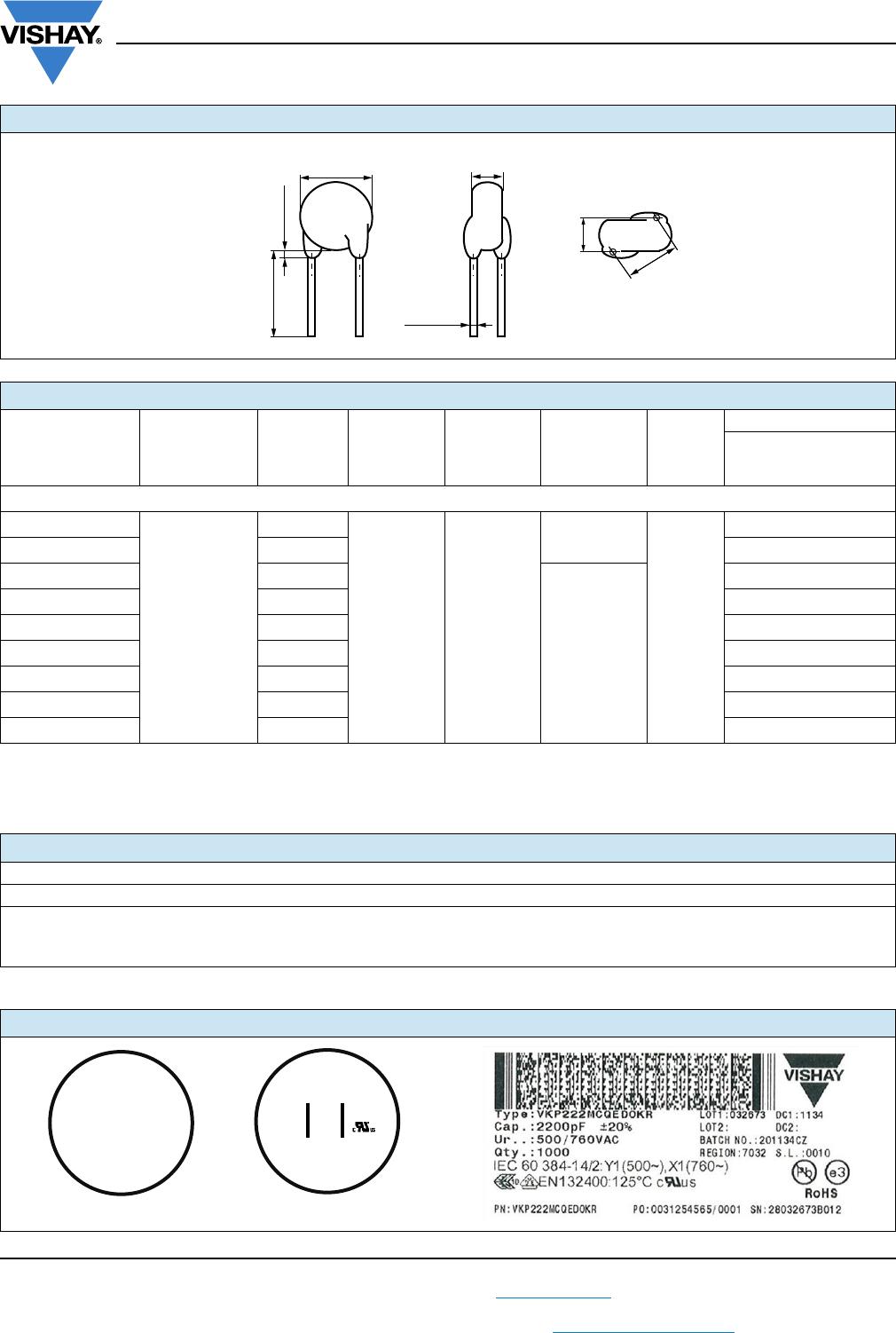
MARKING
Marking indicates series, AC rating, capacitance, tolerance
code, and approvals.
OPERATING TEMPERATURE RANGE
- 40 °C to + 125 °C
TEMPERATURE CHARACTERISTICS
Class 2 Y5U
SECTIONAL SPECIFICATIONS
Climatic category (according to EN 60058-1)
Class 2 40/125/21B
APPROVALS
IEC 60384-14.3
UL 60384-14.1
CSA E60384-1:03 2
nd
edition, CSA E60384-14:09 2
nd
edition
FEATURES
• Complying with IEC 60384-14 3
rd
edition
• High reliability
• Wide range of different leadstyles
• Small dimensions
• Singlelayer AC Disc capacitors
• Material categorization: For definitions of compliance
please see www.vishay.com/doc?99912
APPLICATIONS
• X1, Y1 according to IEC 60384-14.3
• Across-the-line
•Line-by-pass
• Antenna coupling
DESIGN
The capacitors consist of ceramic disc both sides of which
are silver plated. Connection leads are made of tinned
copper having diameters of 0.6 mm or 0.8 mm.
The capacitors may be supplied with straight or kinked
leads having a lead spacing of 10.0 mm or 12.5 mm.
Coating is made of blue colored flame retardant epoxy resin
in accordance with UL 94 V-0.
CAPACITANCE RANGE
470 pF to 4.7 nF
TOLERANCE ON CAPACITANCE
± 10 %, ± 20 %
RATED VOLTAGE
• X1: 760 V
AC
, 50 Hz (IEC 60384-14.3)
760 V
AC
, 50 Hz/60 Hz (US/UL/CSA 60384-14)
• Y1: 500 V
AC
, 50 Hz (IEC 60384-14.3)
500 V
AC
, 50 Hz/60 Hz (US/UL/CSA 60384-14)
TEST VOLTAGE
• 4000 V
AC
, 50 Hz, 2 s Component test (100 %)
• 4000 V
AC
, 50 Hz, 60 s Random sampling test (destructive)
• 4000 V
AC
, 50 Hz, 60 s Voltage proof of coating (destructive)
INSULATION RESISTANCE AT 500 V
DC
10 000 M (60 s)
DISSIPATION FACTOR
Class 2: Max. 2.5 % (1 kHz)
QUICK REFERENCE DATA
DESCRIPTION VALUE
Ceramic Class 2
Ceramic Dielectric Y5U
Voltage (V
AC
) 760 500
Min. Capacitance (pF) 470
Max. Capacitance (pF) 4700
Mounting Radial