NB3V110xC Series
www.onsemi.com
8
t
r
Q
n
80% V
OH
−V
OL
CLKIN
t
f
20% V
OH
−V
OL
V
OH
V
OL
t
PLH
V
DD
/2
Q
n
V
DD
/2
CLKIN
t
PHL
Figure 7. Pulse Skew t
sk(p)
and Propagation Delay
t
PLH
/t
PHL
Figure 8. Rise/Fall Times t
r
/t
f
Note: t
sk(p)
= |t
PLH
− t
PHL
|
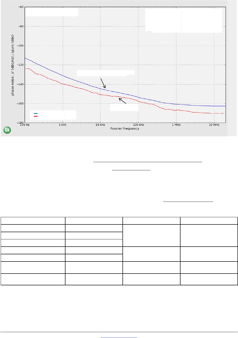
Figure 9. Typical NB3V110xC Phase Noise Plot at f
Carrier
= 100 MHz, V
DD
= 3.3 V, 255C
r
Output
F_carrier = 100 MHz
Output (DUT + Source)
Input Source
Integration Range: 12 kHz − 20 MHz
DUT + Source Phase Jitter = 66.92 fs
Input Source Phase Jitter = 36.72 fs
Input Source 100 MHz
The above phase noise data was captured using Agilent
E5052A/B. The data displays the input phase noise and
output phase noise used to calculate the additive phase jitter
at a specified integration range. The additive RMS phase
jitter contributed by the device (integrated between 12 kHz
and 20 MHz) is 55.94 fs. The additive RMS phase jitter
performance of the fan out buffer is highly dependent on the
phase noise of the input source.
To obtain the most precise additive phase noise
measurement, it is vital that the source phase noise be
notably lower than that of the DUT. If the phase noise of the
source is greater than the noise floor of the device under test,
the source noise will dominate the additive phase jitter
calculation and lead to an incorrect negative result for the
additive phase noise within the integration range. The
Figure above is a good example of the NB3V110xC source
generator phase noise having a significantly lower floor than
the DUT and results in an additive phase jitter of 55.94 fs.
Additive RMS phase jitter + RMS phase jitter of output
2
* RMS phase jitter of input
2
Ǹ
55.94 fs + 66.92 fs
2
* 36.72 fs
2
Ǹ