VS-2N687

VS-2N681, VS-2N5205 Series
www.vishay.com
Vishay Semiconductors
Revision: 19-Nov-15
4
Document Number: 93706
For technical questions within your region: DiodesAmericas@vishay.com
, DiodesAsia@vishay.com, DiodesEurope@vishay.com
THIS DOCUMENT IS SUBJECT TO CHANGE WITHOUT NOTICE. THE PRODUCTS DESCRIBED HEREIN AND THIS DOCUMENT
ARE SUBJECT TO SPECIFIC DISCLAIMERS, SET FORTH AT www.vishay.com/doc?91000
Note
(1)
JEDEC registered value
Fig. 1 - Maximum Allowable Case Temperature
vs. Average On-State Current,
2N681 Series
Fig. 2 - Maximum On-State Voltage vs. Current,
2N681 Series
THERMAL AND MECHANICAL SPECIFICATIONS
PARAMETER SYMBOL TEST CONDITIONS 2N681-92 2N5205-07 UNITS
Operating junction and
storage temperature range
T
J
, T
Stg
-65 to 125
(1)
-40 to 125
(1)
°C
Maximum internal thermal resistance,
junction to case
R
thJC
DC operation 1.5 1.5
(1)
°C/W
Typical thermal resistance,
case to sink
R
thCS
Mounting surface, smooth, flat and greased 0.35 0.35
Mounting torque
± 10 %
to nut
Lubricated threads
(Non-lubricated threads)
20 (27.5) lbf · in
0.23 (0.32) kgf · cm
2.3 (3.1) N · m
to device Lubricated threads
25 lbf · in
0.29 kgf · cm
2.8 N · m
Approximate weight
14 14 g
0.49 0.5 oz.
Case style TO-208AA (TO-48)
Average
On-State Current Over Full Cycle (A)
Maximum Allowable Case Temperature (°C)
0 2 4 6 8 10 12 14 16 18 20 22 24
0
20
40
60
80
100
120
140
160
180
+30°
+60°
+90°
+120°
+180°
DC
Conduction Period
Ø
Sinusoidal Current Waveform
T
J
= 125 °C
Instantaneous On-State Current (A)
Instantaneous On-State Voltage (V)
01234567
1.0
4
10
200
4
10
2
4
10
-1
T
J
= 125 °C
T
J
= 25 °C
VS-2N681, VS-2N5205 Series
www.vishay.com
Vishay Semiconductors
Revision: 19-Nov-15
5
Document Number: 93706
For technical questions within your region: DiodesAmericas@vishay.com
, DiodesAsia@vishay.com, DiodesEurope@vishay.com
THIS DOCUMENT IS SUBJECT TO CHANGE WITHOUT NOTICE. THE PRODUCTS DESCRIBED HEREIN AND THIS DOCUMENT
ARE SUBJECT TO SPECIFIC DISCLAIMERS, SET FORTH AT www.vishay.com/doc?91000
Fig. 3 - Maximum Low Level On-State Power Loss vs.
Current (Sinusoidal Current Waveform),
2N681 Series
Fig. 4 - Maximum High Level On-State Power Loss vs. Current
(Sinusoidal Current Waveform),
2N681 Series
Fig. 5 - Gate Characteristics,
2N681 Series
Fig. 5a - Area of All Possible Triggering Points vs. Temperature,
2N681 Series
Fig. 6 - Maximum Transient Thermal Impedance, Junction to Case, vs. Pulse Duration,
2N681 Series
0
0
10
20
50
60
70
30
40
4 8
12 16 20 24 28 32 36
Average Forward Power Loss
Over Full Cycle (W)
Average
On-State Current Over Full Cycle (A)
+30°
+60°
+90°
+120°
+180°
DC
Conduction Angle
Ø
T
J
= 125 °C
Sinusoidal
Current
Waveform
Controlled
Rectier
Turned
Fully On
I
F
-Average
Forward Power Loss
Over Full Cycle (W)
Average
On-State Current Over Full Cycle (A)
1.0
1.0 10 10
2
4
10
4
44 10
3
4
10
2
4
10
3
4
10
4
T
J
= 125 °C
Sinusoidal Current Waveform
Controlled Rectier
Turned Fully On
Conduction Angle
Ø
+30°
+60°
+90°
+120°
+180°
DC
Instantaneous Gate Voltage (V)
Instantaneous Gate Current (A)
Maximum Allowable
Instantaneous Gate
Power Dissipation
5.0 W
Area of Certain Triggering
Area of All Possible
Triggering Points
0 0.2 0.4 0.6 0.8 1.0 1.2
0
1
2
3
4
5
6
7
8
9
10
Gate Voltage (V)
Gate Current (mA)
0
1
2
3
0 25 50 75 100 125
-65 °C
25 °C
125 °C
V
GD
(Max.) = 0.25 V
t
-
Square Wave Pulse Duration (s)
Z
thJC
-
Transient Thermal Impedance (°C/W)
Free Convection
Mounted on Innite Heatsink
and 4" x 4" x 1/16" Copper Fin
Forced Convection at 1000 LFM
Long Time Durations
Innite Heatsink
1.0 10 10
2
4
10
-2
44410
3
410
4
4
10
-1
10
-1
10
-5
10
-4
10
-3
44410
-2
410
-1
4
10
-6
4
1.0
4
10
-2
10
-1
4
1.0
4
10
1
Short Time Durations
VS-2N681, VS-2N5205 Series
www.vishay.com
Vishay Semiconductors
Revision: 19-Nov-15
6
Document Number: 93706
For technical questions within your region: DiodesAmericas@vishay.com
, DiodesAsia@vishay.com, DiodesEurope@vishay.com
THIS DOCUMENT IS SUBJECT TO CHANGE WITHOUT NOTICE. THE PRODUCTS DESCRIBED HEREIN AND THIS DOCUMENT
ARE SUBJECT TO SPECIFIC DISCLAIMERS, SET FORTH AT www.vishay.com/doc?91000
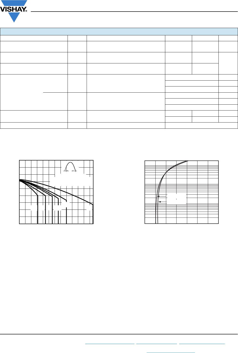
Fig. 7 - Maximum Non-Repetitive Surge Current vs.
Number of Current Pulses,
2N681 Series
Fig. 8 - Maximum Allowable Case Temperature vs. Average
On-State Current (Sinusoidal Current Waveform),
2N5205 Series
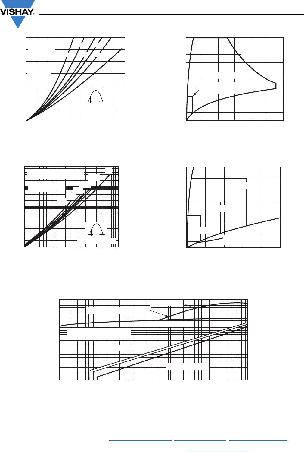
Fig. 9 - Maximum Allowable Case Temperature vs.
Average On-State Current (Rectangular Current Waveform),
2N5205 Series
Fig. 10 - Maximum Low-Level On-State Power Loss vs.
Average On-State Current (Sinusoidal Current Waveform),
2N5205 Series
Fig. 11 - Maximum High-Level On-State Power Loss vs.
Average On-State Current (Sinusoidal Current Waveform),
2N5205 Series
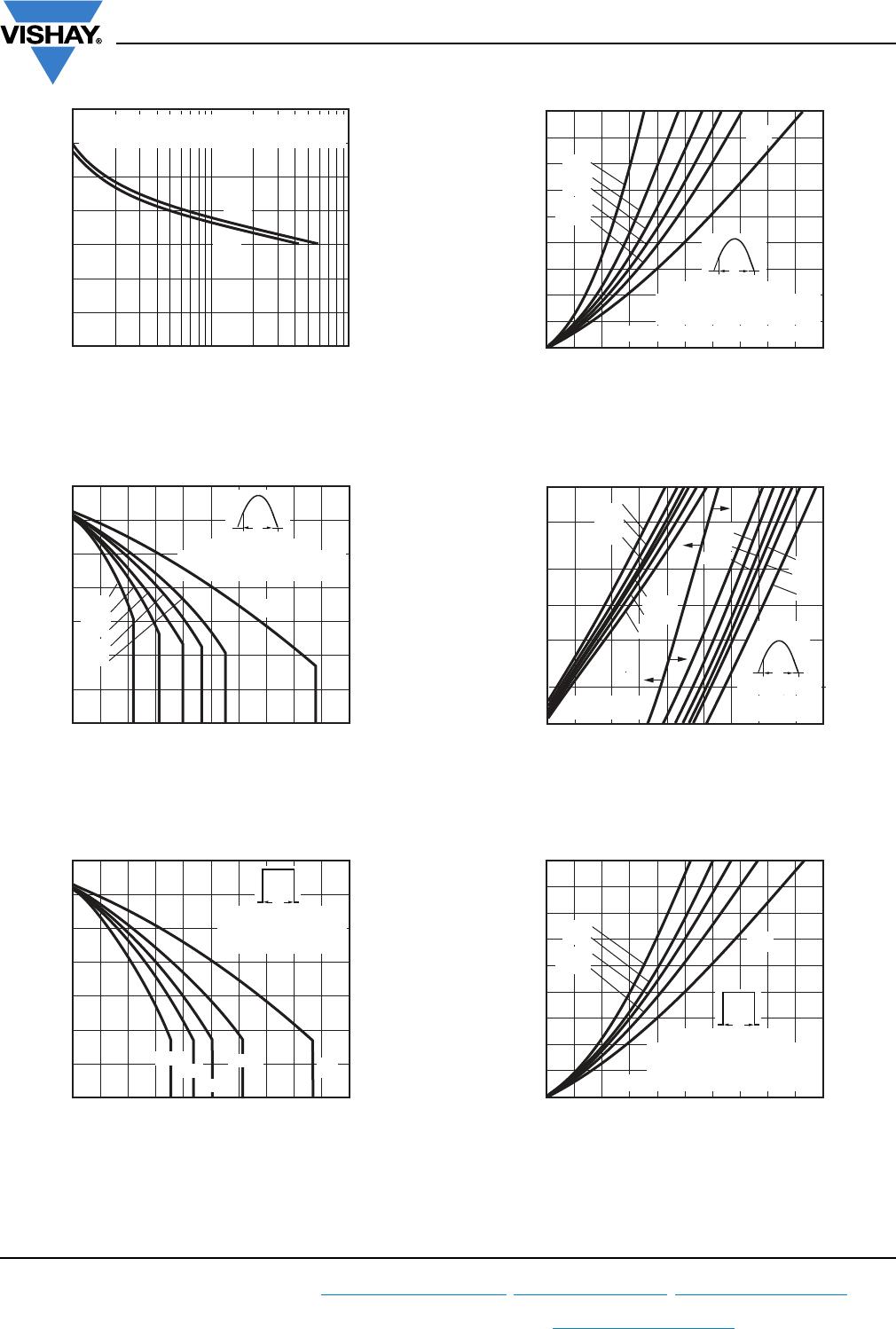
Fig. 12 - Maximum Low-Level On-State Power Loss vs.
Average On-State Current (Rectangular Current Waveform),
2N5205 Series
Peak Half Sine Wave On-State Current (A)
Number Of Equal Amplitude
Half Cycle Current Pulses (N)
0
50
100
150
02468
10 20 40 60
60 Hz
50 Hz
At Any Maximum Rated Load Condition
And With Rated V
RRM
Applied Following Surge
Average
On-State Current Over Full Cycle (A)
Maximum Allowable Case Temperature (°C)
0
0
4 8 12 16 20 24 28 32 36 40
20
40
60
80
100
120
140
+30°
+60°
+90°
+120°
+180°
Conduction Period
Ø
Sinusoidal Current Waveform
T
J
= 125 °C
DC
Average
On-State Current Over Full Cycle (A)
Maximum Allowable Case Temperature (°C)
0
0
4 8 12 16 20 24 28 32 36 40
20
40
60
80
100
120
140
Conduction Period
Rectangular Current
Waveform T
J
= 125 °C
Ø
+60°
+90°
+120°
+180°
DC
Average Forward Power Loss
Over Full Cycle (W)
Average
On-State Current Over Full Cycle (A)
0
0
5 101520 25303540 4550
10
20
30
40
50
60
70
80
90
Conduction Angle
Ø
Sinusoidal Current Waveform
T
J
= 125 °C
Controlled Rectier Turned Fully On
+30°
+60°
+90°
+120°
+180°
DC
1.0
1.0 10 10
2
5
2
5
2
25 25 2510
3
10
2
10
2
10
5
2
5
2
10
4
10
3
I
F
-Average
Forward Power Loss
Over Full Cycle (W)
Average
On-State Current Over Full Cycle (A)
+30°
+60°
+90°
+120°
+180°
DC
+30°
+60°
+90°
+120°
+180°
DC
Controlled Rectier
Turned Fully On
Conduction Angle
Ø
Sinusoidal Current
Waveform
T
J
= 125 °C
Average Forward Power Loss
Over Full Cycle (W)
Average
On-State Current Over Full Cycle (A)
0
0
51015202530
35 40 45 50
10
20
30
40
50
60
70
80
90
Conduction Period
Rectangular Current Waveform
T
J
= 125 °C
Controlled Rectier Turned Fully On
+60°
+90°
+120°
+180°
DC
Ø

VS-2N687

Mfr. #:
Manufacturer:
Vishay Semiconductors
Description:
SCRs 300 Volt 25 Amp
Lifecycle:
New from this manufacturer.
Delivery:
DHL FedEx Ups TNT EMS
Payment:
T/T Paypal Visa MoneyGram Western Union