NXP Semiconductors
BT136X-600E
4Q Triac
BT136X-600E All information provided in this document is subject to legal disclaimers. © NXP Semiconductors N.V. 2015. All rights reserved
Product data sheet 30 April 2015 3 / 13
7. Limiting values
Table 4. Limiting values
In accordance with the Absolute Maximum Rating System (IEC 60134).
Symbol Parameter Conditions Min Max Unit
V
DRM
repetitive peak off-state voltage - 600 V
I
T(RMS)
RMS on-state current full sine wave; T
h
≤ 92 °C; Fig. 1; Fig. 2;
Fig. 3
- 4 A
full sine wave; T
j(init)
= 25 °C;
t
p
= 20 ms; Fig. 4; Fig. 5
- 25 AI
TSM
non-repetitive peak on-state
current
full sine wave; T
j(init)
= 25 °C;
t
p
= 16.7 ms
- 27 A
I
2
t I
2
t for fusing
t
p
= 10 ms; SIN - 3.1
A
2
s
I
G
= 20 mA; T2+ G+ - 50 A/µs
I
G
= 20 mA; T2+ G- - 50 A/µs
I
G
= 50 mA; T2- G+ - 10 A/µs
dI
T
/dt rate of rise of on-state current
I
G
= 20 mA; T2- G- - 50 A/µs
I
GM
peak gate current - 2 A
P
GM
peak gate power - 5 W
P
G(AV)
average gate power over any 20 ms period - 0.5 W
T
stg
storage temperature -40 150 °C
T
j
junction temperature - 125 °C
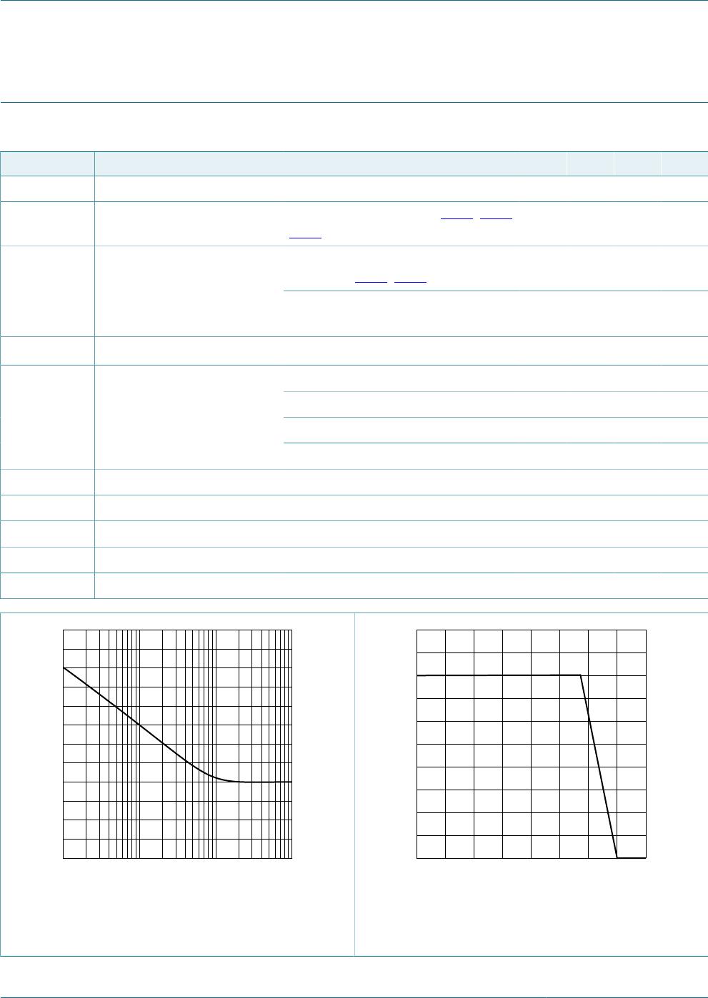
aaa-009685
4
8
12
I
T(RMS)
(A)
0
surge duration (s)
10
-2
10110
-1
2
6
10
f = 50 Hz; T
h
= 92 °C
Fig. 1. RMS on-state current as a function of surge
duration; maximum values
T
h
(°C)
-50 1501000 50
aaa-009556
2
3
1
4
5
I
T(RMS)
(A)
0
Fig. 2. RMS on-state current as a function of heatsink
temperature; maximum values

