DATASHEET
REAL-TIME CLOCK WITH SERIAL I
2
C INTERFACE IDT1339
IDT®
REAL-TIME CLOCK WITH SERIAL I
2
C INTERFACE 1
IDT1339 REV S 031014
General Description
The IDT1339 serial real-time clock (RTC) is a low-power
clock/date device with two programmable time-of-day
alarms and a programmable square-wave output. Address
and data are transferred serially through an I
2
C bus. The
clock/date provides seconds, minutes, hours, day, date,
month, and year information. The date at the end of the
month is automatically adjusted for months with fewer than
31 days, including corrections for leap year. The clock
operates in either the 24-hour or 12-hour format with
AM/PM indicator. The IDT1339 has a built-in power-sense
circuit that detects power failures and automatically
switches to the backup supply, maintaining time, date, and
alarm operation.
Applications
• Handhelds (GPS, POS terminals)
• Consumer Electronics (Set-Top Box, Digital Recording,
Network Applications)
• Office (Fax/Printers, Copiers)
• Medical (Glucometer, Medicine Dispensers)
• Telecomm (Routers, Switches, Servers)
• Other (Thermostats, Vending Machines, Modems, Utility
Meters)
Features
• Real-Time Clock (RTC) counts seconds, minutes, hours,
day, date, month, and year with leap-year compensation
valid up to 2100
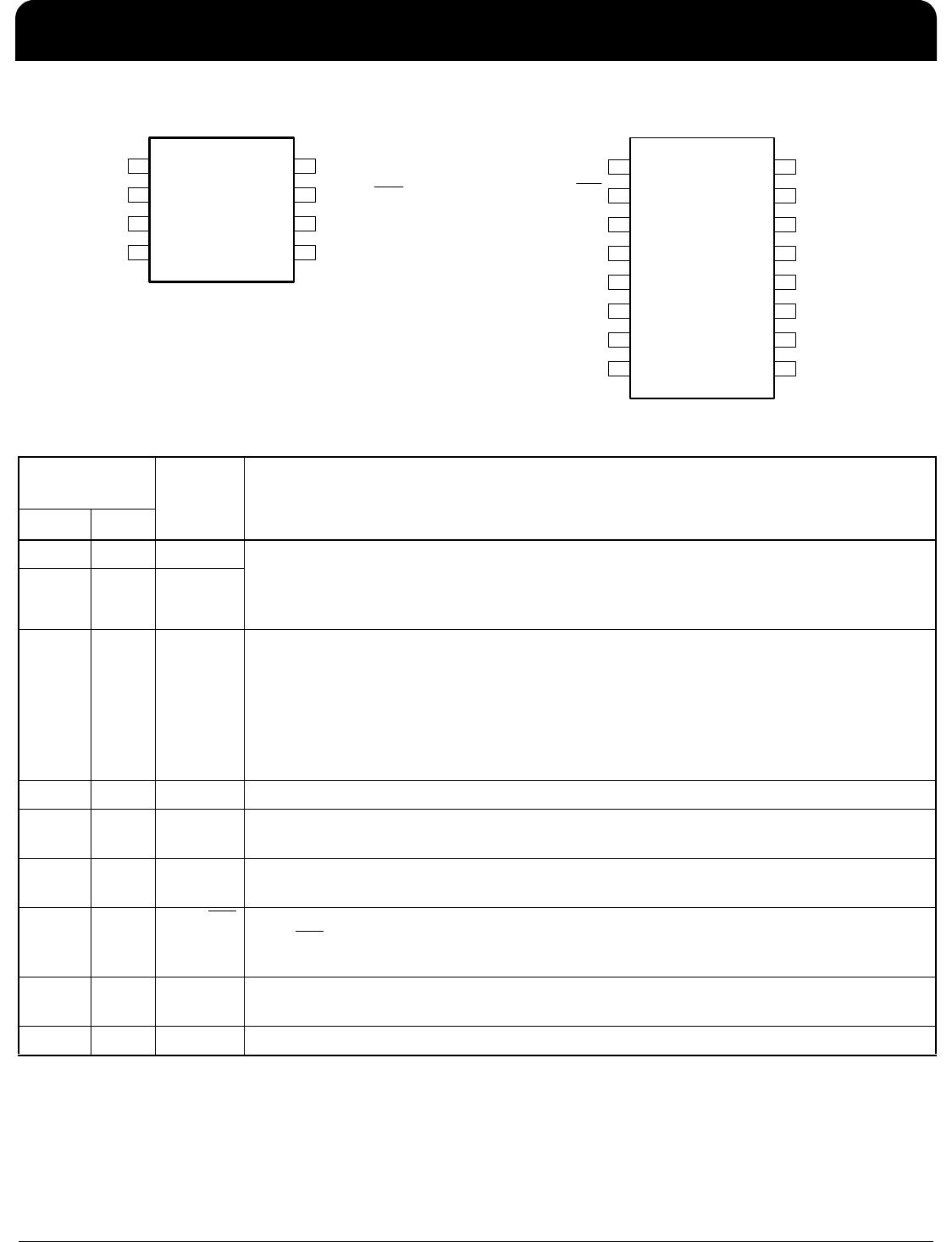
• Packaged in 8-pin MSOP, 8-pin SOIC, or 16-pin SOIC
(surface-mount package with an integrated crystal)
• Fast mode I
2
C Serial interface
• Two time-of-day alarms
• Programmable square-wave output
• Oscillator stop flag
• Automatic power-fail detect and switch circuitry
• Trickle-charge capability
• Industrial temperature range (-40 to +85°C)
• Underwriters Laboratory (UL) recognized
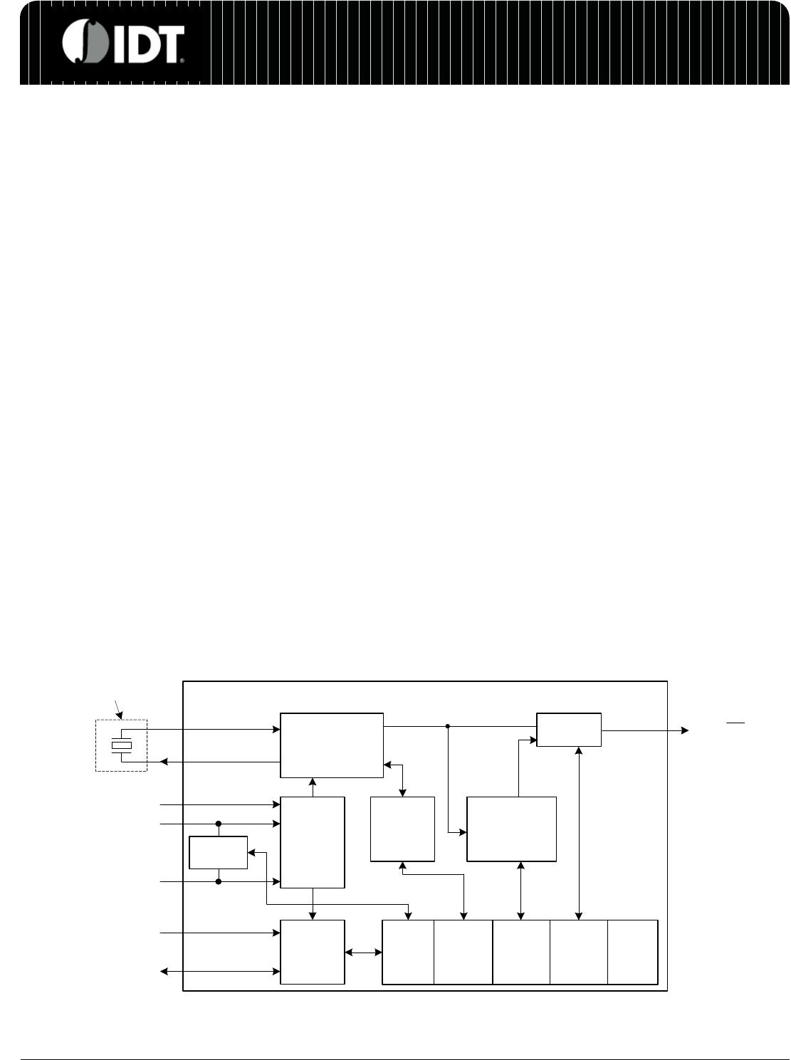
Block Diagram
VCC
GND
V
BACKUP
SCL
SDA
Crystal inside package
for 16-pin SOIC ONLY
X1
X2
1 Hz/4.096 kHz/
8.192 kHz/32.768 kHz
SQW/INT
Power
Control
I
2
C
Interface
32.768 kHz
Oscillator and
Divider
Control
Logic
MUX/
Buffer
Clock,
Calendar
Counter
1 Byte
Control
7 Bytes
Buffer
Trickle
Charger
Byte
7 Bytes
Alarm
Trickle
Charger
1 Byte
Status