I
NTEGRATED
C
IRCUITS
D
IVISION
IX4426-27-28
R05 www.ixysic.com 13
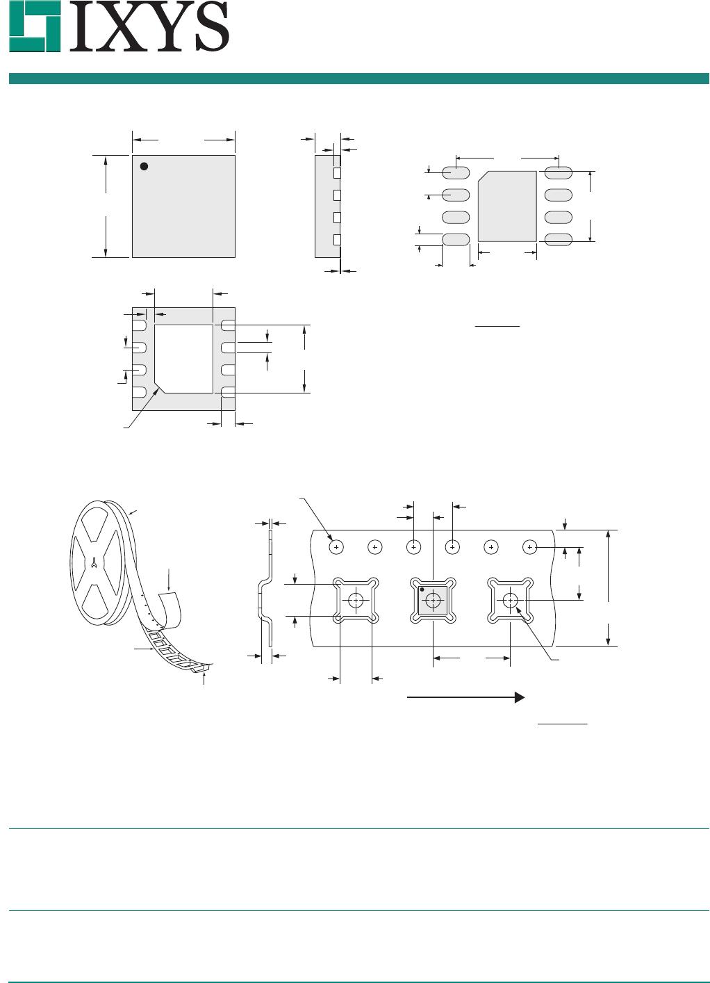
5.4.3 “M” Package (8-Pin DFN)
5.4.4 “M” Package Tape & Reel
Dimensions
mm
(inches)
NOTES:
1. The exposed metal pad on the back of the package should
be connected to GND. Pad is not suitable for carrying current.
2. Terminal width (0.30±0.05) is measured between
0.15mm and 0.30mm from the terminal tip.
3. Bilateral coplanarity zone applies to the exposed
heat sink slug as well as the terminals.
MIN 0.00 / MAX 0.05
(MIN 0.000 / MAX 0.002)
Pin 1
Pin 1 Pin 8
C0.35 x 45º
(C0.014 x 45º)
1.65±0.05
(0.065±0.002)
0.65 BSC
(0.026 BSC)
0.30±0.05
(0.012±0.002)
2.00±0.05
(0.079±0.002)
0.40±0.05
(0.016±0.002)
3.00 BSC
(0.118 BSC)
3.00 BSC
(0.118 BSC)
0.85±0.05
(0.033±0.002)
0.203 REF
(0.008 REF)
MIN 0.2
(MIN 0.008)
Recommended PCB Land Pattern
3.00
(0.118)
0.35
(0.014)
0.80
(0.031)
2.05
(0.081)
1.70
(0.067)
0.65
(0.026)
NOTES:
1. 10 sprocket hole pitch cumulative tolerance ±0.2
2. Camber not to exceed 1mm in 100mm
3. Material black Advantek Polystyrene
4. A0 and B0 measured on a plane 0.3mm above the bottom of the pocket
5. K0 measured from a plane on the inside bottom of the pocket to the top surface of the carrier
6. Pocket position relative to the sprocket hole measured as true position of pocket, not pocket hole
7. Cover tape width 9.3±0.1mm
K
0
=1.10
(0.043)
B
0
=3.30
(0.130)
2.00 ± 0.05
(0.079 ± 0.002)
4.00 Note #1
(0.157)
12.00 ± 0.30
(0.472 ± 0.012)
5.50 ± 0.05
(0.217 ± 0.002)
1.75 ± 0.10
(0.069 ± 0.004)
∅1.50 (MIN)
(∅0.059 MIN)
∅1.55 ± 0.05
(0.061 ± 0.002)
Embossment
Embossed Carrier
Top Cover
Tape Thickness
0.102 MAX.
(0.004 MAX.)
330.2 DIA.
(13.00 DIA.)
8.00
(0.315)
A
0
=3.30
(0.130)
0.30 ± 0.05
(0.012 ± 0.002)
User direction of feed
Dimensions
mm
(inches)
Pin 1
For additional information please visit our website at: www.ixysic.com
IXYS Integrated Circuits Division makes no representations or warranties with respect to the accuracy or completeness of the contents of this publication and reserves the right to make
changes to specifications and product descriptions at any time without notice. Neither circuit patent licenses nor indemnity are expressed or implied. Except as set forth in IXYS Integrated
Circuits Division’s Standard Terms and Conditions of Sale, IXYS Integrated Circuits Division assumes no liability whatsoever, and disclaims any express or implied warranty, relating to its
products including, but not limited to, the implied warranty of merchantability, fitness for a particular purpose, or infringement of any intellectual property right.
The products described in this document are not designed, intended, authorized or warranted for use as components in systems intended for surgical implant into the body, or in other
applications intended to support or sustain life, or where malfunction of IXYS Integrated Circuits Division’s product may result in direct physical harm, injury, or death to a person or severe
property or environmental damage. IXYS Integrated Circuits Division reserves the right to discontinue or make changes to its products at any time without notice.
Specification: DS-IX4426-27-28_R05
©Copyright 2015, IXYS Integrated Circuits Division
All rights reserved. Printed in USA.
8/20/2015