CGA Series
High Temperature Application
Type: CGA2 [EIA CC0402], CGA3 [EIA CC0603], CGA4 [EIA CC0805],
CGA5 [EIA CC1206], CGA6 [EIA CC1210], CGA8 [EIA CC1812], CGA9 [EIA CC2220]
Series Name
Dimensions L x W (mm)
Temperature Characteristics
Rated Voltage (DC)
Nominal Capacitance (pF)
Capacitance
Tolerance
Packaging Style
Nominal Thickness
Code Length Width Terminal
2
1.00 ± 0.05 0.50 ± 0.05
0.10 min.
3
1.60 ± 0.10 0.80 ± 0.10
0.20 min.
4
2.00 ± 0.20 1.25 ± 0.20
0.20 min.
5
3.20 ± 0.20 1.60 ± 0.20
0.20 min.
6
3.20 ± 0.40 2.50 ± 0.30
0.20 min.
8
4.50 ± 0.40 3.20 ± 0.40
0.20 min.
9
5.70 ± 0.40 5.00 ± 0.40
0.20 min.
Code Voltage (DC)
1C 16V
1E 25V
1H 50V
Code Voltage (DC)
2A 100V
2E 250V
2W 450V
2J 630V
Code Tolerance
C
±0.25pF
D
±0.50pF
J
±5%
K
± 10%
M
±20%
Code Style
A 178 mm Reel, 4 mm Pitch
B 178 mm Reel, 2 mm Pitch
K 178 mm Reel, 8 mm Pitch
Temperature
Characteristics
Temperature
Range
NP0
0±30ppm/°C -55 to +150°C
X8R
±15% -55 to +150°C
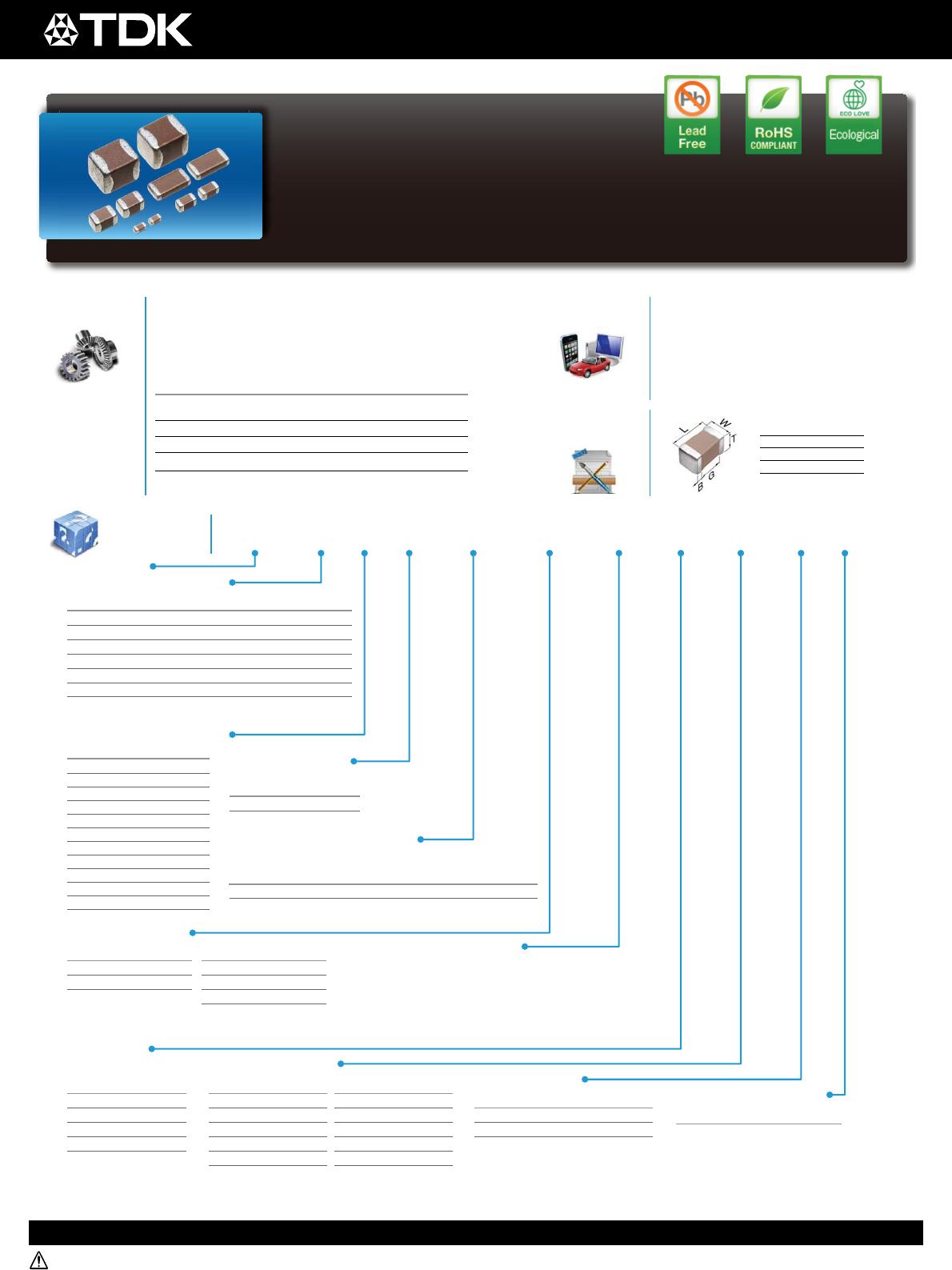
CGA • 6 • P • 3 • X8R • 1C • 106 • K • 250 • A • B
Code Thickness
050 0.50 mm
060 0.60 mm
080 0.80 mm
085 0.85 mm
115 1.15 mm
125 1.25 mm
Special Reserved Code
Code Description
A, B TDK Internal Code
Code Thickness
B0.50 mm
C0.60 mm
E0.80 mm
F0.85 mm
H1.15 mm
J1.25 mm
L1.60 mm
M2.00 mm
N2.30 mm
P2.50 mm
Q2.80 mm
R3.20 mm
Thickness T Code (mm)
Symbol Condition
2
2 × R.V.
3
1.5 × R.V.
Voltage Condition
for Life Test
• With a maximum temperature of 150°C and a capacitance
change within ±15%, the series is suited for devices that operate
in high-temperature environments.
• Excellent DC bias properties.
• AEC-Q200 compliant.
• Automotive applications (engine rooms)
• Peripheral circuits of IGDT, SiC, GaN used
at high temperature environments
• Sensor Module
• Smoothing and decoupling applications for
other devices that operate at high
temperature
Features Applications
L Body Length
W Body Width
T Body Height
B Terminal Width
G Terminal Spacing
Shape &
Dimensions
Code Thickness
160 1.60 mm
200 2.00 mm
230 2.30 mm
250 2.50 mm
280 2.80 mm
320 3.20 mm
The capacitance is expressed in three digit codes and in units
of pico Farads (pF). The first and second digits identify the first
and second significant figures of the capacitance. The third
digit identifies the multiplier. R designates a decimal point.
Ex. 0R2 = 0.2pF; 103 = 10,000pF; 105 = 1,000,000pF =
100nF = 1ȝF
*Dimension tolerance are typical values
Catalog Number
Construction
Temperature Coefficient or
Capacitance Change
Parameters Specifications
Temperature
Characteristics
-55 to 150°C
¨C/C: ±15% or 0±30ppm
Operating Temperature
-55 to +150°C
Dissipation Factor 5% maximum
Insulation Resistance 10 G or 500 M • ȝF minimum
Voltage Proof
2.5 • RV or 3 • RV for 1~5s
Charge/Discharge 50 mA
Page 2
MULTILAYER CERAMIC CHIP CAPACITORS
20150410 / mlcc_automotive_hightemp_en
Please be sure to request delivery specifi cations that provide further details on the features and specifi cations of the products for proper and safe use.
Please note that the contents may change without any prior notice due to reasons such as upgrading.