CGA2B2NP01H102J050BA

CGA2(1005) [EIA CC0402]
Capacitance
Range Chart
Capacitance Range Chart
Temperature Characteristics: NP0 (0 ± 30ppm/ºC), X8R (±15%)
Rated Voltage: 100V (2A), 50V (1H), 25V (1E), 16V (1C)
Capacitance
(pF)
Code Tolerance
NP0 X8R
1H
(
2A
(100V)
2A
(100V) 50V)
1H
(50V)
1E
(25V)
1C
(16V)
C: ±0.25pF
D: ±0.50pF
J:±5%
K:±10%
M: ± 20%
0.50 mm
1
1.5
2
2.2
3
3.3
4
4.7
5
6
6.8
7
8
9
10
12
15
18
22
27
33
39
47
56
68
82
100
120
150
180
220
270
330
390
470
560
680
820
1,000
1,500
2,200
3,300
4,700
6,800
10,000
15,000
22,000
33,000
47,000
010
1R5
020
2R2
030
3R3
040
4R7
050
060
6R8
070
080
090
100
120
150
180
220
270
330
390
470
560
680
820
101
121
151
181
221
271
331
391
471
561
681
821
102
152
222
332
472
682
103
153
223
333
473
Standard Thickness
Page 3
MULTILAYER CERAMIC CHIP CAPACITORS
20150410 / mlcc_automotive_hightemp_en
  
Please be sure to request delivery speci cations that provide further details on the features and speci cations of the products for proper and safe use.
Please note that the contents may change without any prior notice due to reasons such as upgrading.
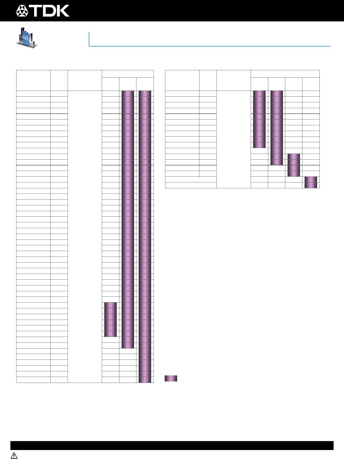
CGA3(1608) [EIA CC0603]
Capacitance
Range Chart
Capacitance Range Chart
Temperature Characteristics: NP0 (0 ± 30ppm/ºC), X8R (±15%)
Rated Voltage: 250V (2E), 100V (2A), 50V(1H), 25V (1E), 16V (1C)
0.80 mm
Capacitance
(pF)
Code Tolerance
Standard Thickness
Capacitance
(pF)
Code Tolerance
NP0
2A
(100V)
2E
(250V)
1H
(50V)
1
2
2
2
3
3
4
5
5
6
7
7
8
9
10
12
15
18
22
27
33
39
47
56
68
82
100
120
150
180
220
270
330
390
470
560
680
820
1,000
1,200
1,500
1,800
2,200
2,700
3,300
3,900
4,700
5,600
6,800
8,200
10,000
010
1R5
020
2R2
030
3R3
040
4R7
050
060
6R8
070
080
090
100
120
150
180
220
270
330
390
470
560
680
820
101
121
151
181
221
271
331
391
471
561
681
821
102
122
152
182
222
272
332
392
472
562
682
822
103
C: ± 0.25pF
D: ± 0.50pF
J: ± 5%
X8R
2A
(100V)
1H
(50V)
1E
(25V)
1C
(16V)
102
152
222
332
472
682
103
153
223
333
473
683
104
154
224
334
474
1,000
1,500
2,200
3,300
4,700
6,800
10,000
15,000
22,000
33,000
47,000
68,000
100,000
150,000
220,000
330,000
470,000
K: ± 10%
M: ± 20%
Page 4
MULTILAYER CERAMIC CHIP CAPACITORS
20150410 / mlcc_automotive_hightemp_en
  
Please be sure to request delivery speci cations that provide further details on the features and speci cations of the products for proper and safe use.
Please note that the contents may change without any prior notice due to reasons such as upgrading.
Page 5
MULTILAYER CERAMIC CHIP CAPACITORS
20150410 / mlcc_automotive_hightemp_en
  
Please be sure to request delivery speci cations that provide further details on the features and speci cations of the products for proper and safe use.
Please note that the contents may change without any prior notice due to reasons such as upgrading.
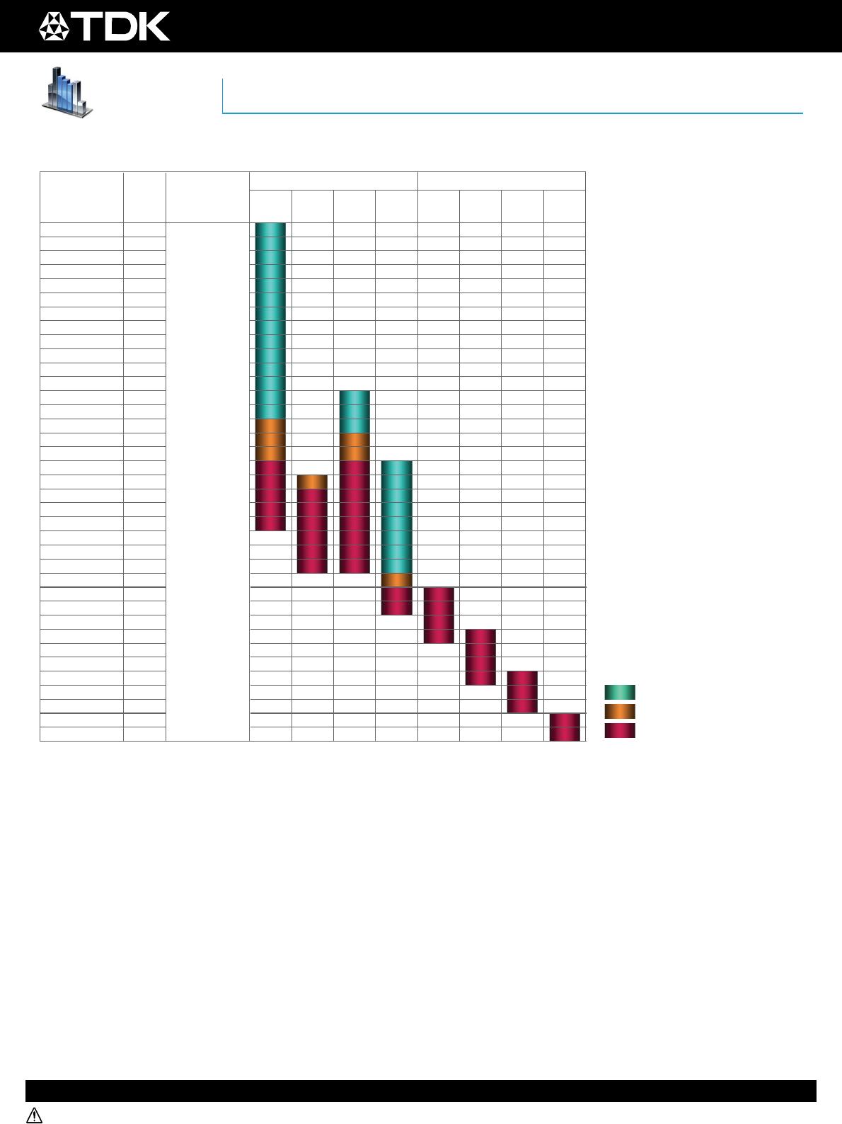
CGA4(2012) [EIA CC0805]
Capacitance
Range Chart
Capacitance Range Chart
Temperature Characteristics: NP0 (0 ± 30ppm/ºC), X8R (±15%)
Rated Voltage: 450V(2W), 250V(2E), 100V (2A), 50V (1H), 25V (1E), 16V (1C)
0.60 mm
0.85 mm
1.25 mm
Capacitance
(pF)
Code Tolerance
Standard Thickness
NP0 X8R
2A
(100V)
2E
(250V)
2W
(450V)
1H
(50V)
2A
(100V)
1H
(50V)
1E
(25V)
1C
(16V)
101
121
151
181
221
271
331
391
471
561
681
821
102
122
152
182
222
272
332
392
472
562
682
822
103
153
223
333
473
683
104
154
224
334
474
684
105
100
120
150
180
220
270
330
390
470
560
680
820
1,000
1,200
1,500
1,800
2,200
2,700
3,300
3,900
4,700
5,600
6,800
8,200
10,000
15,000
22,000
33,000
47,000
68,000
100,000
150,000
220,000
330,000
470,000
680,000
1,000,000
J: ± 5%
K: ± 10%
M: ± 20%

CGA2B2NP01H102J050BA

Mfr. #:
Manufacturer:
TDK
Description:
Multilayer Ceramic Capacitors MLCC - SMD/SMT 1000pF 50volts NP0 5%
Lifecycle:
New from this manufacturer.
Delivery:
DHL FedEx Ups TNT EMS
Payment:
T/T Paypal Visa MoneyGram Western Union