16
Integrated Silicon Solution, Inc. — www.issi.com
Rev. F
03/03/09
IS42S32400D
AC ELECTRICAL CHARACTERISTICS
(1,2,3)
-6 -7
Symbol Parameter Min. Max. Min. Max. Units
t
CK3 Clock Cycle Time CAS Latency = 3 6 — 7 — ns
tCK2 CAS Latency = 2 8 — 10 — ns
tAC3 Access Time From CLK CAS Latency = 3 — 5.4 — 5.4 ns
tAC2 CAS Latency = 2 — 6.5 — 6.5 ns
tCHI CLK HIGH Level Width 2.5 — 2.5 — ns
tCL CLK LOW Level Width 2.5 — 2.5 — ns
tOH3 Output Data Hold Time CAS Latency = 3 2.7 — 2.7 — ns
tOH2 CAS Latency = 2 2.7 — 3 — ns
tLZ Output LOW Impedance Time 0 — 0 — ns
tHZ Output HIGH Impedance Time 2.7 5.4 2.7 5.4 ns
tDS Input Data Setup Time
(2)
1.5 — 1.5 — ns
tDH Input Data Hold Time
(2)
0.8 — 0.8 — ns
tAS Address Setup Time
(2)
1.5 — 1.5 — ns
tAH Address Hold Time
(2)
0.8 — 0.8 — ns
tCKS CKE Setup Time
(2)
1.5 — 1.5 — ns
tCKH CKE Hold Time
(2)
0.8 — 0.8 — ns
tCS Command Setup Time (CS, RAS, CAS, WE, DQM)
(2)
1.5 — 1.5 — ns
tCH Command Hold Time (CS, RAS, CAS, WE, DQM)
(2)
0.8 — 0.8 — ns
tRC Command Period (REF to REF / ACT to ACT) 60 — 67.5 — ns
tRAS Command Period (ACT to PRE) 42
100K
45
100K
ns
tRP Command Period (PRE to ACT) 18 — 20 — ns
tRCD Active Command To Read / Write Command Delay Time 18 — 20 — ns
tRRD Command Period (ACT [0] to ACT[1]) 12 — 14 — ns
tDPL Input Data To Precharge 12 — 14 — ns
Command Delay time
tDAL Input Data To Active / Refresh
30
—
34
—ns
Command Delay time (During Auto-Precharge)
tMRD Mode Register Program Time 12 — 15 — ns
tDDE Power Down Exit Setup Time 6 — 7.5 — ns
tXSR Self-Refresh Exit Time 70 — 70 — ns
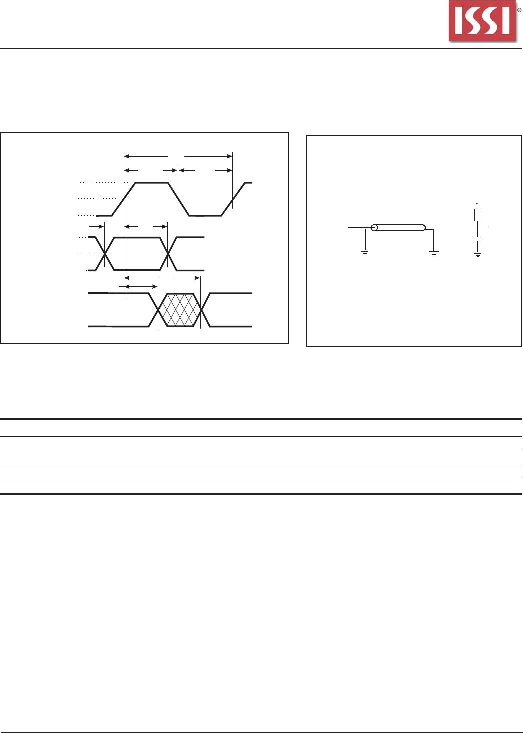
tT Transition Time 1 10 1 10 ns
tREF Refresh Cycle Time (4096) — 64 — 64 ms
Notes:
1. The power-on sequence must be executed before starting memory operation.
2. Measured with t
T = 1 ns. If clock rising time is longer than 1ns, (tR /2 - 0.5) ns should be added to the parameter.
3.
The reference level is 1.4V when measuring input signal timing. Rise and fall times are measured between V
IH
(min.) and V
IL
(max).