SQM200JB-6R2

Through-hole resisTors
DIMENSIONS
Unit: mm
STYLE DIMENSION
Normal Non-Ind. H W S P
SQM200 NSM200 20±1.5 11.0±1.0 7.0±1.0 5
+2-1
SQM300 NSM300 25±1.5 12.0±1.0 8.0±1.0 5
+2-1
SQM500 NSM500 25±1.5 13.0±1.0 9.0±1.0 5
+2-1
SQM700 NSM700 39±1.5 13.0±1.0 9.0±1.0 5
+2-1
SQM10A NSM10A 51±1.5 13.0±1.0 9.0±1.0 5
+2-1
SQM10S NSM10S 35±1.5 16.0±1.0 12.0±1.0 7
+2-1
FEATURES
Power Rating 2W, 3W, 5W, 7W, 10W
Resistance Tolerance ±5%
T.C.R. ±250ppm/°C, -80~500ppm/°C (depends on value)
DERATING CURVE TEMPERATURE RISE
Cement Resistors
Vertical Lead Type
Normal Style [ SQM Series ]
Non-Inductive Style [ NSM Series ]
INTRODUCTION
The SQM Series are ceramic housed resistors
with fiberglass based wirewound or ceramic
rod wirewound or metal oxide core. The
NSM Series are ceramic housed low-inductive
resistors with ceramic rod wirewound core.
The materials used and the construction
techniques ensure excellent flame resistance,
arc resistance and moisture resistance as well
as self-extinguishing capabilities. They will
withstand the most rigorous loading test.
As resistors in radio and television receivers,
hazardous conditions such as smoking and
redheat can be completely prevented by the
proper choice of power resistors.
30025020015010050-50 0
100
80
60
40
20
70
3W-5W
7W-10W
2W
155 27540 °C
Rated Load
Ambient Temperature (°C)
(%)
12010080604020
250
200
150
100
50
10W
7W
5W
3W
2W
Temperature Rise
Rated Load (%)
(°C)
ø08±0.05
H
P
3.5±1
W
S
Revision: 201304
63
Note: Rated Continuous Working Voltage (RCWV) = Power Rating x Resistance Value or Max. working voltage listed above, whichever less.
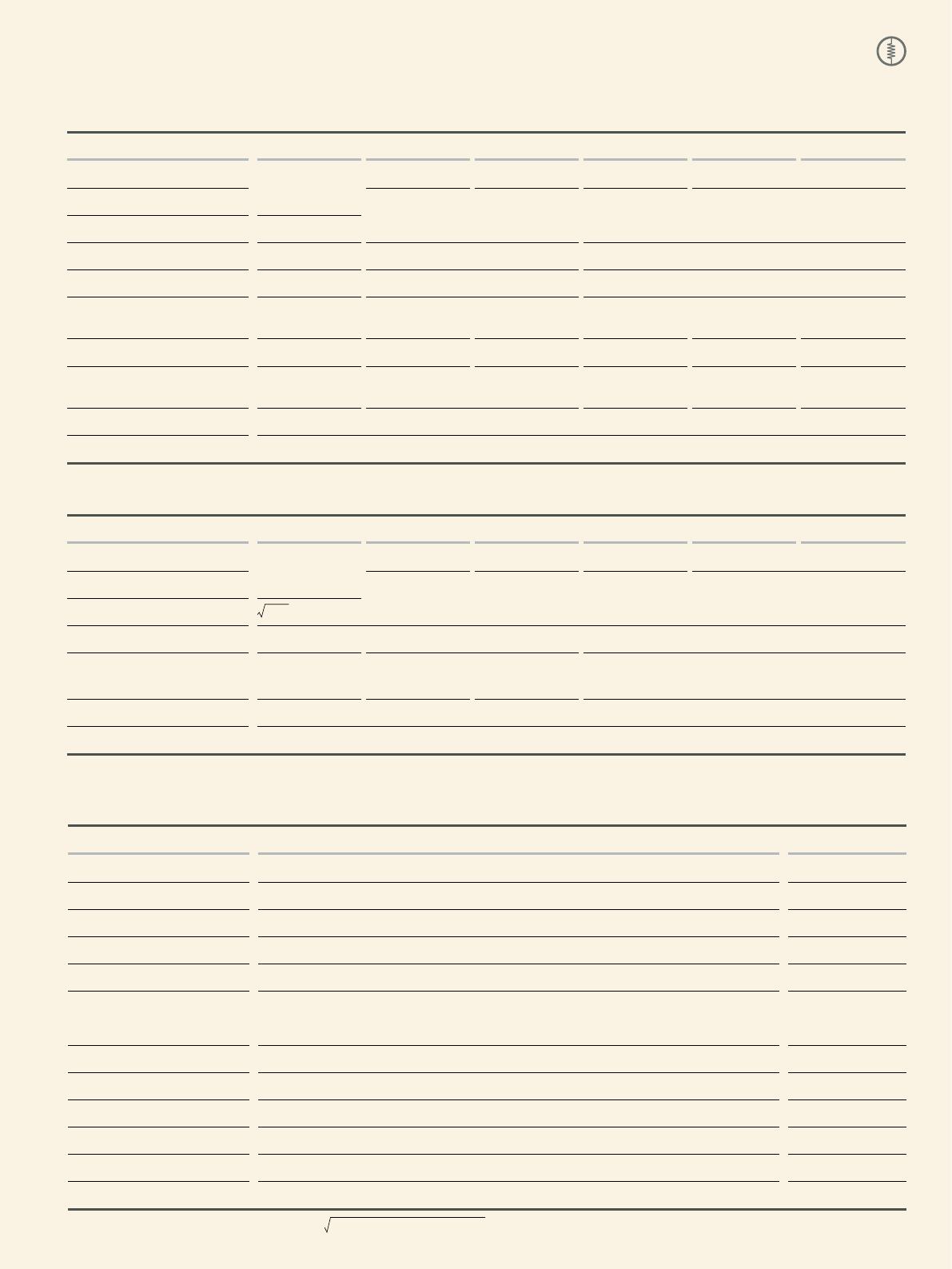
ELECTRICAL CHARACTERISTICS
NORMAL STYLE
STYLE SQM200 SQM300 SQM500 SQM700 SQM10A SQM10S
Power Rating at 40°C 3W 5W 7W 10W
Power Rating at 70°C 2W
Maximum Working Voltage 250V 350V 500V
Maximum Overload Voltage 500V 700V 1,000V
Voltage Proof on Insulation 500V 700V 1,000V
Resistance Range
(Ceramic based wirewound)
0.1Ω - 36Ω 0.1Ω - 68Ω 0.1Ω - 130Ω 0.1Ω - 330Ω 0.1Ω - 510Ω 0.1Ω - 270Ω
Resistance Range (Metal Oxide Film)
39Ω - 1MΩ 75Ω - 1MΩ 150Ω - 1MΩ 360Ω - 1MΩ 560Ω - 1MΩ 300Ω - 1MΩ
Resistance Range
(Fiberglass based wirewound)
0.1Ω - 1KΩ 0.1Ω - 4.7KΩ 0.1Ω - 10KΩ 0.1Ω - 16KΩ 0.1Ω - 4.7KΩ
Operating Temp. Range -55°C to +155°C
Temperature Coefcient ±300ppm/°C
NON-INDUCTIVE STYLE
STYLE NSM200 NSM300 NSM500 NSM700 NSM10A NSM10S
Power Rating at 40°C 3W 5W 7W 10W
Power Rating at 70°C 2W
Maximum Working Voltage
PxR
Voltage Proof on Insulation 500V 700V 1,000V
Resistance Range
(Ceramic based wirewound)
0.1Ω - 10Ω 0.1Ω - 30Ω 0.15Ω - 65Ω 0.27Ω - 100Ω
Operating Temp. Range -55°C to +155°C
Temperature Coefcient ±300ppm/°C
Note: Special value is available on request
ENVIRONMENTAL CHARACTERISTICS
PERFORMANCE TEST TEST METHOD APPRAISE
Short Time Overload IEC 60115-1 4.13 2.5 times RCWV for 5 Sec. ±2.0%+0.05Ω
Voltage Proof on Insulation IEC 60115-1 4.7 in V-block for 60 Sec., test voltage by type By type
Temperature Coefcient IEC 60115-1 4.8 -55°C to +155°C By type
Insulation Resistance IEC 60115-1 4.6 in V-block for 60 Sec. >1,000MΩ
Solderability IEC 60115-1 4.17 235±5°C for 3±0.5 Sec. 95% Min. coverage
Solvent Resistance of Marking IEC 60115-1 4.30 IPA for 5±0.5 Min. with ultrasonic
No deterioration of
coatings and markings
Robustness of Terminations IEC 60115-1 4.16 Direct load for 10 Sec. in the direction of the terminal leads ≥2.5kg (24.5N)
Periodic-pulse Overload IEC 60115-1 4.39 4 times RCWV 10,000 cycles (1 Sec. on, 25 Sec. off) ±2.0%+0.05Ω
Damp Heat Steady State IEC 60115-1 4.24 40±2°C, 90-95% RH for 56 days, loaded with 0.1 times RCWV ±5.0%+0.05Ω
Endurance at 70°C IEC 60115-1 4.25 70±2°C at RCWV for 1,000 Hr. (1.5 Hr. on, 0.5 Hr. off) ±5.0%+0.05Ω
Temperature Cycling IEC 60115-1 4.19 -55°C Room Temp. +155°C Room Temp. (5 cycles) ±2.0%+0.05Ω
Resistance to Soldering Heat IEC 60115-1 4.18 260±3°C for 10±1 Sec., immersed to a point 3±0.5mm from the body ±1.0%+0.05Ω
88
EXPLANATIONS OF ORDERING CODE
EXCEPTION:
• Cement series: • JPW series:
<Code 8>: Special packing style code
B: Bulk with wirewound or metal oxide sub-assembly for resistance value
W: Bulk with ceramic based wirewound sub-assembly for resistance value
M: Bulk with metal oxide sub-assembly for resistance value
F: Bulk with Fiberglass based wirewound sub-assembly for resistance value
<Code 10-12>: Without forming code
Example:
SQP500JB-10R
<Code 13-17>: without resistance value code
Example:
JPW-06-T-52-
-12
Code 4 - 6
Power Rating
-05 = ød0.5mm
-06 = ød0.6mm
-07 = ød0.7mm
-08 = ød0.8mm
-10 = ød1.0mm
-14 = ød1.4mm
-12 = 1/6W
-25 = 1/4W
25S = 1/4WS
-50 = 1/2W
50S = 1/2WS
100 = 1W
1WS = 1WS
200 = 2W
2WS = 2WS
204 = 0.4W
207 = 0.6W
300 = 3W
3WS = 3WS
3WM = 3WM
400 = 4W
500 = 5W
5WS = 5WS
5SS = 5WSS
700 = 7W
7WS = 7WS
10A = 10W
20A = 20W
30A = 30W
40A = 40W
50A = 50W
10S = 10WS
15A = 15W
25A = 25W
10B = 100W
25B = 250W
F
Code 7
Tolerance
P = ±0.02 %
A = ±0.05 %
B = ±0.1 %
C = ±0.25%
D = ±0.5 %
F = ±1 %
G = ±2 %
J = ±5 %
K = ±10 %
- = Base on Spec.
T
Code 8
Packing Style
T = Tape/Box
R = Tape/Reel
B = Bulk
F
Code 9
Temperature Coef-
cient of Resistance
- = Base on Spec.
A = ±5 ppm/°C
B = ±10 ppm/°C
C = ±15 ppm/°C
S = ± 20ppm/°C
D = ±25 ppm/°C
E = ±50 ppm/°C
F = ±100 ppm/°C
G = ±200 ppm/°C
H = ±250 ppm/°C
I = ±300 ppm/°C
J = ±350 ppm/°C
52-
Code 10 - 12
Forming Type
26- = 26mm
52- = 52.4mm
73- = 73mm
81- = 81mm
91- = 91mm
F = F Type
FK = FK Type
FKK = FKK Type
FFK = F-form Kink
M = M-Type Forming
MB = M-form W/at
MT = MT Type Forming
MR = MR Type
AV = AVIsert
PN = PANAsert
100R
Code 13 - 17
Resistance Value
0R1 = 0.1
100R = 100
10K = 10,000
10M = 10,000,000
MFR
Code 1 - 3
Series Name
See Index

SQM200JB-6R2

Mfr. #:
Manufacturer:
Yageo
Description:
Wirewound Resistors - Through Hole
Lifecycle:
New from this manufacturer.
Delivery:
DHL FedEx Ups TNT EMS
Payment:
T/T Paypal Visa MoneyGram Western Union