SMZG3788B thru SMGZ3809B
www.vishay.com
Vishay General Semiconductor
Revision: 25-May-12
2
Document Number: 88458
For technical questions within your region: DiodesAmericas@vishay.com
, DiodesAsia@vishay.com, DiodesEurope@vishay.com
THIS DOCUMENT IS SUBJECT TO CHANGE WITHOUT NOTICE. THE PRODUCTS DESCRIBED HEREIN AND THIS DOCUMENT
ARE SUBJECT TO SPECIFIC DISCLAIMERS, SET FORTH AT www.vishay.com/doc?91000
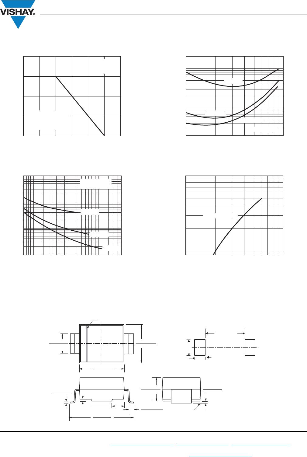
Note
(1)
Maximum steady state power dissipation is 1500 mW at T
L
= 75 °C (fig. 1)
Note
(1)
AEC-Q101 qualified
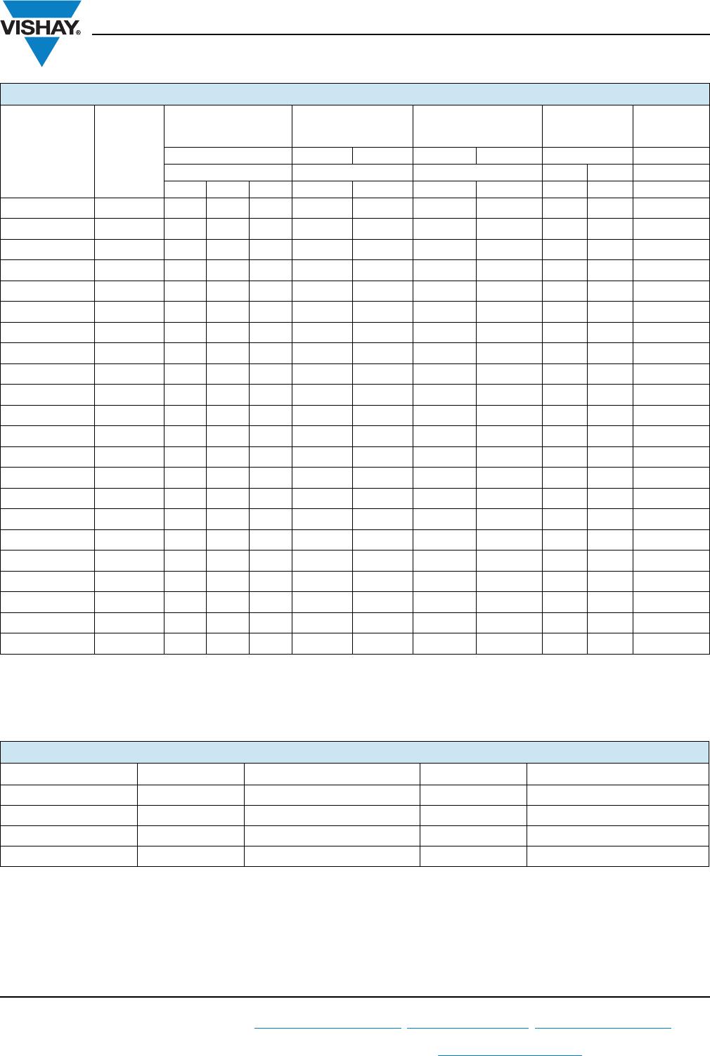
ELECTRICAL CHARACTERISTICS (T
A
= 25 °C unless otherwise noted)
PART
NUMBER
DEVICE
MARKING
CODE
ZENER VOLTAGE
RANGE
TEST CURRENT
MAXIMUM ZENER
IMPEDANCE
MAXIMUM
REVERSE
CURRENT
MAXIMUM
ZENER
CURRENT
(1)
V
Z
AT I
ZT
I
ZT
I
ZK
Z
ZT
AT I
ZT
Z
ZK
AT I
ZK
I
R
AT V
R
I
ZM
VmA μA V mA
MIN. NOM. MAX. MAX. MAX. MAX. MAX.
SMZG3788B VL
8.65 9.1 9.56 41.2 0.50 4.0 1000 50 7.0 140
SMZG3789B WB
9.50 10 10.5 37.5 0.25 5.0 1000 50 7.6 125
SMZG3790B WD
10.5 11 11.6 34.1 0.25 6.0 650 10 8.4 115
SMZG3791B WF
11.4 12 12.6 31.2 0.25 7.0 550 5.0 9.1 105
SMZG3792B WH
12.4 13 13.7 28.8 0.25 7.5 550 5.0 9.9 98
SMZG3793B WJ
14.3 15 15.8 25.0 0.25 9.0 600 5.0 11.4 85
SMZG3794B WL
15.2 16 16.8 23.4 0.25 10.0 600 5.0 12.2 80
SMZG3795B XB
17.1 18 18.9 20.8 0.25 12.0 650 5.0 13.7 70
SMZG3796B XD
19.0 20 21.0 18.7 0.25 14.0 650 5.0 15.2 62
SMZG3797B XF
20.9 22 23.1 17.0 0.25 17.5 650 5.0 16.7 56
SMZG3798B XH
22.8 24 25.2 15.6 0.25 19.0 700 5.0 18.2 51
SMZG3799B XJ
25.7 27 28.4 13.9 0.25 23.0 700 5.0 20.6 46
SMZG3800B XL
28.5 30 31.5 12.5 0.25 26.0 750 5.0 22.8 41
SMZG3801B YB
31.4 33 34.7 11.4 0.25 33.0 800 5.0 25.1 38
SMZG3802B YD
34.2 36 37.8 10.4 0.25 38.0 850 5.0 27.4 35
SMZG3803B YF
37.1 39 41.0 9.6 0.25 45.0 900 5.0 29.7 31
SMZG3804B YH
40.9 43 45.2 8.7 0.25 53.0 950 5.0 32.7 28
SMZG3805B YJ
44.7 47 49.4 8.0 0.25 67.0 1000 5.0 35.8 26
SMZG3806B YL
48.5 51 53.6 7.3 0.25 70.0 1100 5.0 38.8 24
SMZG3807B ZB
53.2 56 58.8 6.7 0.25 86.0 1300 5.0 42.6 22
SMZG3808B ZD
58.9 62 65.1 6.0 0.25 100.0 1500 5.0 47.1 20
SMZG3809B ZF
64.6 68 71.4 5.5 0.25 120.0 1700 5.0 51.7 18
ORDERING INFORMATION (Example)
PREFERRED P/N UNIT WEIGHT (g) PREFERRED PACKAGE CODE BASE QUANTITY DELIVERY MODE
SMZG3788B-E3/52 0.096 52 750 7" diameter plastic tape and reel
SMZG3788B-E3/5B 0.096 5B 3200 13" diameter plastic tape and reel
SMZG3788BHE3/52
(1)
0.096 52 750 7" diameter plastic tape and reel
SMZG3788BHE3/5B
(1)
0.096 5B 3200 13" diameter plastic tape and reel