Expand menu
Hello, Sign in
My Account
0
Cart
Home
Products
Sensors
Semiconductors
Passive Components
Connectors
Power
Electromechanical
Optoelectronics
Circuit Protection
Integrated Circuits - ICs
Main Products
Manufacturers
Blog
Services
About OMO
About Us
Contact Us
Check Stock
LTC6992HDCB-2#TRPBF
P1-P3
P4-P6
P7-P9
P10-P12
P13-P15
P16-P17
PBRN113E_SER_1
© NXP B.V
. 2007. All rights reser
ved.
Product data sheet
Rev
. 01 — 1 March 2007
7 of 17
NXP Semiconductors
PBRN113E series
NPN 800 mA, 40 V BISS RETs; R1 = 1 k
Ω
, R2 = 1 k
Ω
Ceramic PCB, Al
2
O
3
, standard footprint
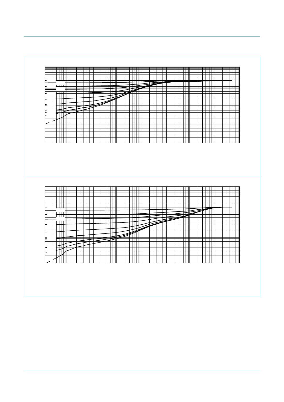
Fig 5.
T
ransient thermal impedance from junction to ambient as a function of pulse duration f
or
SO
T23 (TO-236AB) and SO
T346 (SC-59A/T
O-236); typical values
FR4 PCB, standard f
ootpr
int
Fig 6.
T
ransient thermal impedance from junction to ambient as a function of pulse duration f
or
SO
T54 (SC-43A/TO-92); typical v
alues
006aab002
10
1
10
2
10
3
Z
th(j-a)
(K/W)
10
−
1
10
−
5
10
10
−
2
10
−
4
10
2
10
−
1
t
p
(s)
10
−
3
10
3
1
0.75
0.50
0.33
0.20
0.01
0.10
0.05
0.02
0
δ
= 1
006aab003
10
−
5
10
10
−
2
10
−
4
10
2
10
−
1
t
p
(s)
10
−
3
10
3
1
10
2
10
10
3
Z
th(j-a)
(K/W)
1
0.75
0.50
0.33
0.20
0.01
0.10
0.05
0.02
0
δ
= 1
PBRN113E_SER_1
© NXP B.V
. 2007. All rights reser
ved.
Product data sheet
Rev
. 01 — 1 March 2007
8 of 17
NXP Semiconductors
PBRN113E series
NPN 800 mA, 40 V BISS RETs; R1 = 1 k
Ω
, R2 = 1 k
Ω
7.
Characteristics
[1]
Pulse test: t
p
≤
300
µ
s;
δ≤
0.02.
T
able 8.
Characteristics
T
amb
=2
5
°
C unless otherwise specified.
Symbol
P
arameter
Conditions
Min
Ty
p
Max
Unit
I
CBO
collector-base cut-off
current
V
CB
=3
0V
;
I
E
=0A
-
-
100
nA
I
CEO
collector-emitter cut-off
current
V
CE
=3
0V
;
I
B
=0A
-
-
0.5
µ
A
I
EBO
emitter-base cut-off
current
V
EB
=5V
;
I
C
=0A
--4
m
A
h
FE
DC current gain
V
CE
=5V
;
I
C
=5
0m
A
40
75
-
V
CE
=5V
;
I
C
= 300 mA
[1]
180
300
-
V
CE
=5V
;
I
C
= 600 mA
[1]
250
400
-
V
CE
=5V
;
I
C
= 800 mA
[1]
270
420
-
V
CEsat
collector-emitter
saturation v
oltage
I
C
= 50 mA;
I
B
= 2.5 mA
-
2
53
5m
V
I
C
= 200 mA;
I
B
=1
0m
A
-
6
08
5m
V
I
C
= 500 mA;
I
B
=1
0m
A
[1]
-
160
220
mV
I
C
= 600 mA;
I
B
=6m
A
[1]
-
320
550
mV
I
C
= 800 mA;
I
B
=8m
A
[1]
-
0.68
1.15
V
V
I(off)
off-state input voltage
V
CE
=5V
;
I
C
= 100
µ
A
0.6
1
1.5
V
V
I(on)
on-state input voltage
V
CE
= 0.3 V
;
I
C
=2
0m
A
1
1.3
1.8
V
R1
bias resistor 1 (input)
0.7
1
1.3
k
Ω
R2/R1
bias resistor ratio
0.9
1
1.1
C
c
collector capacitance
V
CB
=1
0V
;
I
E
=i
e
=0A
;
f=1M
H
z
-7
-p
F
PBRN113E_SER_1
© NXP B.V
. 2007. All rights reser
ved.
Product data sheet
Rev
. 01 — 1 March 2007
9 of 17
NXP Semiconductors
PBRN113E series
NPN 800 mA, 40 V BISS RETs; R1 = 1 k
Ω
, R2 = 1 k
Ω
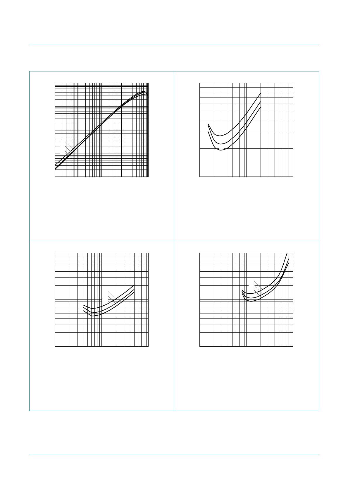
V
CE
=5V
(1)
T
amb
= 100
°
C
(2)
T
amb
=2
5
°
C
(3)
T
amb
=
−
40
°
C
I
C
/I
B
=2
0
(1)
T
amb
= 100
°
C
(2)
T
amb
=2
5
°
C
(3)
T
amb
=
−
40
°
C
Fig 7.
DC current gain as a function of collector
current; typical values
Fig 8.
Collector-emitter saturation v
oltage as a
function of collector current; typical values
I
C
/I
B
=5
0
(1)
T
amb
= 100
°
C
(2)
T
amb
=2
5
°
C
(3)
T
amb
=
−
40
°
C
I
C
/I
B
= 100
(1)
T
amb
= 100
°
C
(2)
T
amb
=2
5
°
C
(3)
T
amb
=
−
40
°
C
Fig 9.
Collector-emitter saturation v
oltage as a
function of collector current; typical values
Fig 10.
Collector-emitter saturation v
oltage as a
function of collector current; typical values
006aab004
I
C
(mA)
10
−
1
10
3
10
2
11
0
1
10
10
2
10
3
h
FE
10
−
1
(1)
(2)
(3)
006aab005
I
C
(mA)
10
10
3
10
2
10
−
1
V
CEsat
(V)
10
−
2
(1)
(2)
(3)
I
C
(mA)
10
10
3
10
2
006aab006
10
−
1
1
V
CEsat
(V)
10
−
2
(1)
(2)
(3)
I
C
(mA)
10
10
3
10
2
006aab007
10
−
1
1
V
CEsat
(V)
10
−
2
(1)
(2)
(3)
P1-P3
P4-P6
P7-P9
P10-P12
P13-P15
P16-P17
LTC6992HDCB-2#TRPBF
Mfr. #:
Buy LTC6992HDCB-2#TRPBF
Manufacturer:
Analog Devices Inc.
Description:
Switching Controllers PWM with 5% to 95% Pulse Width Control
Lifecycle:
New from this manufacturer.
Delivery:
DHL
FedEx
Ups
TNT
EMS
Payment:
T/T
Paypal
Visa
MoneyGram
Western
Union
Products related to this Datasheet
LTC6992HS6-1#TRPBF
LTC6992MPS6-1#TRMPBF
LTC6992CS6-1#TRMPBF
LTC6992CS6-2#TRMPBF
LTC6992HS6-1#TRMPBF
LTC6992IS6-3#TRMPBF
LTC6992IDCB-1#TRMPBF
LTC6992HS6-2#TRMPBF
LTC6992CS6-4#TRMPBF
LTC6992IS6-4#TRMPBF
LTC6992IS6-1#TRMPBF
LTC6992CDCB-1#TRMPBF
LTC6992IS6-2#TRMPBF
LTC6992HS6-3#TRMPBF
LTC6992HDCB-3#TRPBF
LTC6992MPS6-1#TRPBF
LTC6992CDCB-2#TRMPBF
LTC6992CDCB-4#TRMPBF
LTC6992CDCB-3#TRMPBF
LTC6992IDCB-3#TRMPBF
LTC6992IDCB-4#TRMPBF
LTC6992IDCB-2#TRMPBF
LTC6992HS6-4#TRMPBF
LTC6992HDCB-4#TRMPBF
LTC6992HDCB-1#TRMPBF
LTC6992HDCB-3#TRMPBF
LTC6992HDCB-2#TRMPBF
LTC6992MPS6-4#TRMPBF
LTC6992MPS6-3#TRMPBF
LTC6992MPS6-2#TRMPBF
LTC6992CS6-3#TRPBF
LTC6992CDCB-2#TRPBF
LTC6992CS6-4#TRPBF
LTC6992CS6-2#TRPBF
LTC6992CS6-1#TRPBF
LTC6992CDCB-1#TRPBF