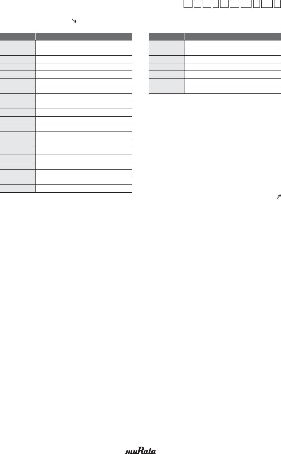
GRM21BR61E106MA73L

(Part Number)
1Product ID 2Series
Chip Monolithic Ceramic Capacitors for General
GA
GC
GJ
GM
GQ
GR
GX
KR
LL
ZR
2
3
H
4
8
M
A
D
M
3
4
7
J
M
M
3
M
A
L
M
R
A
B
Products based on the Electrical Appliance and Material Safety Law of Japan
Safety standard certified type
For implantable Medical Devices (Non-critical circuits)
Audio signal low distortion type
Acoustic noise reduction type
High Q type for High frequency
Wire bondable vertical electrode type
Wire bondable/AuSn solderable type
High Q type for High frequency and High power
High eective capacitance & High allowable ripple current
For Ethernet LAN & primary-secondary coupling of DC-DC converters
Product limited to camera flash units
So termination type
General purpose products
Water repellent type
Metal terminal type/High eective capacitance & High allowable ripple current
Metal terminal type
8 terminal low ESL type
LW reversed low ESL type
10 terminal low ESL type
ESR controlled low ESL type
On interposer substrates (Chip < interposer substrates)
On interposer substrates (Chip
>
=
interposer substrates)
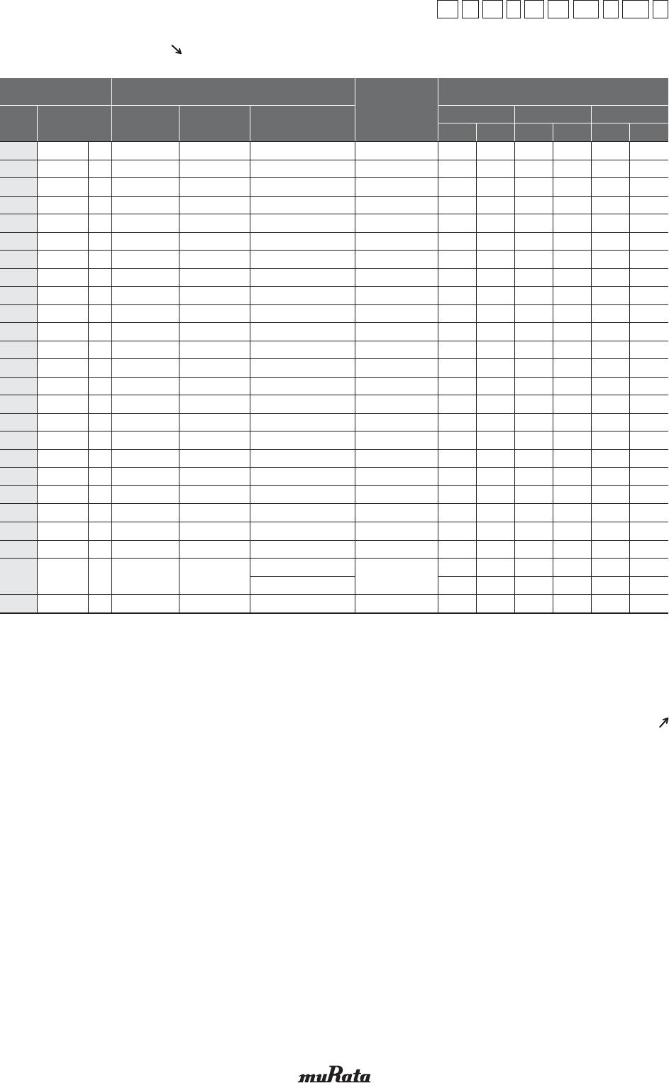
Product ID Code Series
3Chip Dimensions (LxW) (Except ZRA)
2
GR
1
M
3
18
4
8
5
B1
6
1H
7
102
8
K
9
A01
:
D
Code
0.25x0.125mm
0.4x0.2mm
0.38x0.38mm
0.5x0.25mm
0.6x0.3mm
0.5x0.5mm
0.8x0.8mm
0.6x1.0mm
1.0x0.5mm
1.6x0.8mm
1.8x1.0mm
2.0x1.25mm
2.8x2.8mm
3.2x1.6mm
3.2x2.5mm
4.5x2.0mm
4.5x3.2mm
5.7x2.8mm
5.7x5.0mm
Dimensions (LxW)
008004
01005
015015
015008
0201
0202
0303
02404
0402
0603
0704
0805
1111
1206
1210
1808
1812
2211
2220
EIA
01
02
0D
MD
03
05
08
1U
15
18
JN
21
22
31
32
42
43
52
55
3Dimensions (LxW) (ZRA Only)
Code
2.4x1.65mm
Dimensions (LxW)
21
o Part Numbering
Continued on the following page.
(Part Number)
2
GR
1
M
3
18
4
8
5
B1
6
1H
7
102
8
K
9
A01
:
D
4Height Dimension (T) (KRp Only)
Code
E
F
K
L
Q
T
W
1.8mm
1.9mm
2.7mm
2.8mm
3.7mm
4.8mm
6.4mm
Dimension (T)
A
B
C
D
E
M
N
Q
R
S
X
1.0mm
1.25mm
1.6mm
2.0mm
2.5mm
1.15mm
1.35mm
1.5mm
1.8mm
2.8mm
Depends on individual standards.
4Height Dimension (T) (Except KRp)
Code
1
2
3
4
5
6
7
8
9
0.125mm
0.2mm
0.3mm
0.4mm
0.5mm
0.6mm
0.7mm
0.8mm
0.85mm
Dimension (T)
Continued from the preceding page.
Continued on the following page.
(Part Number)
2
GR
1
M
3
18
4
8
5
B1
6
1H
7
102
8
K
9
A01
:
D
5Temperature Characteristics
Code
Temperature
Characteristic Codes
Public
STD Code
Reference
Temperature
Temperature Characteristics Capacitance Change Each Temperature (%)
Capacitance Change
or Temperature
Coecient
Operating
Temperature
Range
–55°C
Max.
*6 –10°C
Temperature
Range
CG
SL
CH
CJ
UJ
CK
C0G
X8G
C0H
U2J
CGJ
B *1
B
X5S
X7S
X6S
X7T
X6T
X7U
R *1
X5R
X7R
R *1
X7T
X7R
JIS
JIS
JIS
JIS
JIS
JIS
EIA
*2
EIA
EIA
*2
JIS
JIS
EIA
EIA
EIA
EIA
EIA
EIA
JIS
EIA
EIA
JIS
EIA
EIA
20°C
20°C
20°C
20°C
20°C
20°C
25°C
25°C
25°C
25°C
20°C
20°C
20°C
25°C
25°C
25°C
25°C
25°C
25°C
20°C
25°C
25°C
20°C
25°C
25°C
1C
1X
2C
3C
3U
4C
5C
5G
6C
7U
9C
B1
B3
C6
C7
C8
D7
D8
E7
R1
R6
R7
R8
W0
Z7
20 to 125°C
20 to 85°C
20 to 125°C
20 to 125°C
20 to 85°C
20 to 125°C
25 to 125°C
25 to 150°C
25 to 125°C
25 to 125°C
*5
20 to 85°C
–25 to 85°C
–25 to 85°C
–55 to 85°C
–55 to 125°C
–55 to 105°C
–55 to 125°C
–55 to 105°C
–55 to 125°C
–55 to 125°C
–55 to 85°C
–55 to 125°C
–25 to 85°C
–55 to 125°C
–55 to 125°C
0±30ppm/°C
+350 to –1000ppm/°C
0±60ppm/°C
0±120ppm/°C
–750±120ppm/°C
0±250ppm/°C
0±30ppm/°C
0±30ppm/°C
0±60ppm/°C
–750±120ppm/°C
0±30ppm/°C
±10%
±10%
±22%
±22%
±22%
+22%, –33%
+22%, –33%
+22%, –56%
±15%
±15%
±15%
±15%
±10% *3
+22%, –33% *4
±15% *7
–55 to 125°C
–55 to 125°C
–55 to 125°C
–55 to 125°C
–25 to 85°C
–55 to 125°C
–55 to 125°C
–55 to 150°C
–55 to 125°C
–55 to 125°C
–55 to 85°C
–25 to 85°C
–25 to 85°C
–55 to 85°C
–55 to 125°C
–55 to 105°C
–55 to 125°C
–55 to 105°C
–55 to 125°C
–55 to 125°C
–55 to 85°C
–55 to 125°C
–25 to 85°C
–55 to 125°C
–55 to 125°C
0.54
-
0.82
1.37
-
2.56
0.58
0.58
0.87
8.78
0.54
-
-
-
-
-
-
-
-
-
-
-
-
-
-
-
Min.
–0.23
-
–0.45
–0.9
-
–1.88
–0.24
–0.24
–0.48
5.04
–0.23
-
-
-
-
-
-
-
-
-
-
-
-
-
-
-
Max.
0.33
-
0.49
0.82
4.94
1.54
0.4
0.4
0.59
6.04
0.33
-
-
-
-
-
-
-
-
-
-
-
-
-
-
-
Min.
–0.14
-
–0.27
–0.54
2.84
–1.13
–0.17
–0.17
–0.33
3.47
–0.14
-
-
-
-
-
-
-
-
-
-
-
-
-
-
-
Max.
0.22
-
0.33
0.55
3.29
1.02
0.25
0.25
0.38
3.84
0.22
-
-
-
-
-
-
-
-
-
-
-
-
-
-
-
Min.
–0.09
-
–0.18
–0.36
1.89
–0.75
–0.11
–0.11
–0.21
2.21
–0.09
-
-
-
-
-
-
-
-
-
-
-
-
-
-
-
*1 Capacitance change is specified with 50% rated voltage applied.
*2 Murata Temperature Characteristic Code.
*3 Apply DC350V bias.
*4 No DC bias.
*5 Rated Voltage 100Vdc max: 25 to 85°C
*6 –25°C (Reference Temperature 20°C) / –30°C (Reference Temperature 25°C)
*7 Range of capacitance change rate with 50% rated voltage applied (See detailed specifications sheet).
Continued from the preceding page.
Continued on the following page.

GRM21BR61E106MA73L

Mfr. #:
Manufacturer:
Description:
Multilayer Ceramic Capacitors MLCC - SMD/SMT 0805 10uF 25volts X5R 20%
Lifecycle:
New from this manufacturer.
Delivery:
DHL FedEx Ups TNT EMS
Payment:
T/T Paypal Visa MoneyGram Western Union