Expand menu
Hello, Sign in
My Account
0
Cart
Home
Products
Sensors
Semiconductors
Passive Components
Connectors
Power
Electromechanical
Optoelectronics
Circuit Protection
Integrated Circuits - ICs
Main Products
Manufacturers
Blog
Services
About OMO
About Us
Contact Us
Check Stock
IRG4PC30KDPBF
P1-P3
P4-P6
P7-P9
P10-P11
IRG4PC30KDPbF
www.irf.com
7
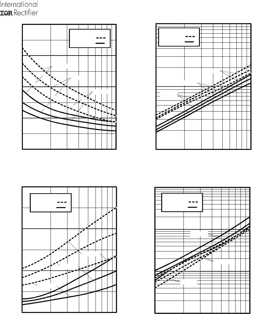
Fig. 14
- Typical
Reverse
Recovery vs.
di
f
/dt
Fig. 15
- Typical
Recovery
Current vs.
di
f
/dt
Fig. 16
- Typical
Stored Charge
vs. di
f
/dt
Fig. 17
- Typical
di
(rec)M
/dt vs.
di
f
/dt
0
200
400
600
100
1000
f
di
/dt - (A/µs
)
RR
Q
-
(nC)
I = 6
.0
A
I = 1
2
A
I = 2
4
A
V = 200V
T
= 12
5°C
T = 2
5
°
C
R
J
J
F
F
F
10
100
1000
10000
100
1000
f
d
i /d
t - (
A/µ
s)
di(r
ec)M
/dt
- (A/µs
)
I = 1
2
A
I =
24A
I = 6
.0
A
F
F
F
V = 200V
T
= 12
5°C
T = 2
5
°
C
R
J
J
0
40
80
120
160
100
1000
f
d
i /d
t - (
A/µ
s)
t
- (ns)
rr
I = 2
4
A
I =
12A
I
= 6.0A
F
F
F
V = 200V
T
= 12
5°C
T = 2
5
°
C
R
J
J
1
10
100
100
1000
f
di
/dt -
(A
/µs)
I
- (A
)
IRRM
I =
6.0A
I = 12
A
I = 24
A
F
F
F
V = 200V
T
= 12
5°C
T = 2
5
°
C
R
J
J
IRG4PC30KDPbF
8
www.irf.com
Same t
y
pe
device
as
D.U
.T.
D.U.T.
430µ
F
80%
of Vc
e
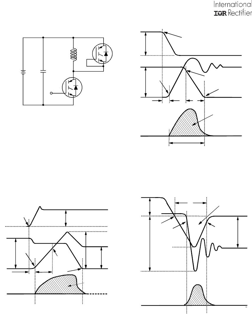
Fig. 18a
-
Test Circuit for Measurement of
I
LM
, E
on
, E
off(diode)
, t
rr
, Q
rr
, I
rr
, t
d(on)
, t
r
, t
d(off)
, t
f
t1
Ic
Vce
t1
t2
90% Ic
10% Vce
td(o
ff)
tf
Ic
5% Ic
t1+
5µ
S
Vce i
c dt
90% Vge
+Vge
∫
Eo
ff =
Fig. 18b
-
Test Waveforms
for Circuit
of Fig. 18a,
Defining
E
off
, t
d(off)
, t
f
∫
Vce ie dt
t2
t1
5% Vce
Ic
Ipk
Vc
c
10% Ic
Vce
t1
t2
DUT VO
LTAGE
AN
D CU
RRE
NT
GATE VOLTA
GE D.U.T.
+Vg
10% +Vg
90% Ic
tr
td(on)
DIODE REVERSE
RECOVERY ENERGY
tx
Eon =
∫
Erec =
t4
t3
Vd id dt
t4
t3
DI
ODE
RE
CO
V
ERY
W
AVEFORMS
Ic
Vpk
10% Vcc
Irr
10% Irr
Vcc
trr
∫
Qr
r =
trr
tx
id
dt
Fig. 18c
-
Test Waveforms
for Circuit of
Fig. 18a,
Defining E
on
,
t
d(on)
,
t
r
Fig. 18d
-
Test
Waveforms for Circuit
of Fig.
18a,
Defining E
rec
, t
rr
, Q
rr
, I
rr
Vd
Ic
dt
Vce
Ic
dt
Ic dt
Vce
Ic
dt
IRG4PC30KDPbF
www.irf.com
9
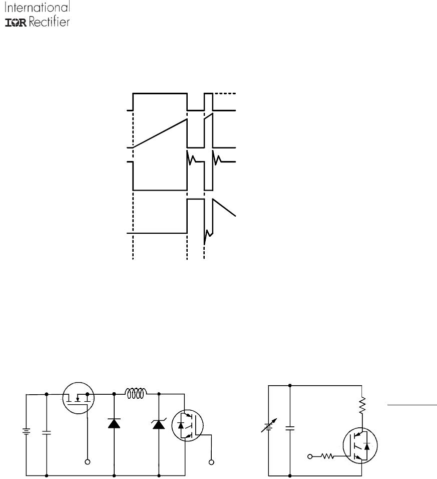
Vg
GATE SIG
NAL
DEVI
CE
UNDE
R T
E
S
T
CURRE
N
T D
.U
.T
.
VOLTAGE
IN
D.U.T.
CURRE
N
T I
N
D1
t0
t1
t2
D.U.T.
V *
c
50V
L
1000V
6000µF
100V
Figure 19. Clamped Inductive Load Test Circuit
Figure 20. Pulsed Collector Current
Test Circuit
R
L
=
480V
4 X I
C
@25°C
0 -
480V
Figure 18e. Macro Waveforms for
Figure 18a's
Test Circuit
P1-P3
P4-P6
P7-P9
P10-P11
IRG4PC30KDPBF
Mfr. #:
Buy IRG4PC30KDPBF
Manufacturer:
Infineon Technologies
Description:
IGBT Transistors 600V UltraFast 8-25kHz
Lifecycle:
New from this manufacturer.
Delivery:
DHL
FedEx
Ups
TNT
EMS
Payment:
T/T
Paypal
Visa
MoneyGram
Western
Union
Products related to this Datasheet
IRG4PC30KDPBF