7
Maxim Integrated
MAX9812/MAX9813
Tiny, Low-Cost, Single/Dual-Input, Fixed-Gain
Microphone Amplifiers with Integrated Bias
Pin Description
Detailed Description
The MAX9812_/MAX9813_ are low-power fixed-gain
microphone amplifiers available in a single- or dual-
input configuration. The gain is set at 10V/V (20dB) with
a 400kHz, -3dB bandwidth. They also feature a low-
noise, integrated microphone input bias voltage.
Single/Dual Input
The MAX9812L/MAX9812H are single-input amplifiers
and the MAX9813L/MAX9813H are dual-input ampli-
fiers. All devices typically have an input impedance of
85kΩ. The inputs to the dual version are controlled
through a fast 2:1 mux, selectable through the IN1/IN2
pin. Driving IN1/IN2 high selects IN1 and driving the
IN1/IN2 low selects IN2. IN1/IN2 is designed to be dri-
ven by a logic high of ≥2V and a logic low
≤0.8V. The IN1/IN2 has a 10µs switching time from one
channel to the other.
PC2001 Low-Noise Microphone BIAS
The MAX9812_/MAX9813_ provide a low-noise voltage
BIAS designed for biasing electret condenser micro-
phone (ECM) cartridges. The BIAS output is regulated
to typically 2.3V for the MAX9812L/MAX9813L and 4V
for the MAX9812H/MAX9813H. In the single-input ver-
sion (MAX9812_), the BIAS output can source up to
1mA. In the dual-input version (MAX9813_), the BIAS
output can source up to 2mA. The MAX9812H/
MAX9813H provides a PC2001-compliant BIAS voltage.
Output Stage
The MAX9812_/MAX9813_ rail-to-rail output (OUT) typical-
ly swings to within 100mV of the rails when driving 10kΩ.
The output DC bias point is set to 1.5V for the MAX9812L/
MAX9813L and 2.5V for the MAX9812H/MAX9813H.
Shutdown Mode
SHDN controls whether the MAX9812_/MAX9813_ is
active or in shutdown mode. Driving SHDN low forces a
low-power (100nA) shutdown mode. In this mode, the
OUT pin is set to a high-impedance state and the BIAS
pin is pulled down (70kΩ). Driving SHDN high enables
the MAX9812_/MAX9813_. SHDN is a high-impedance
input and cannot be left unconnected.
Driving Capacitive Loads
The MAX9812_/MAX9813_ output can drive up to 50pF
of capacitance without sustained oscillations.
Thermal Shutdown
The thermal shutdown feature protects the
MAX9812_/MAX9813_ from destruction due to overheat-
ing caused by shorting the outputs. This protection fea-
ture causes OUT and BIAS to shut down and go high
impedance when the die temperature reaches +140°C.
The device restarts after the die temperature falls below
+120°C.
Applications Information
Power-Up
The MAX9812_/MAX9813_ output typically settles to
95% within 10ms after power-up.
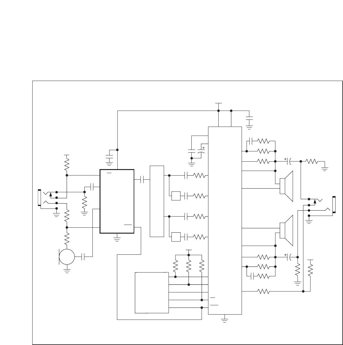
Typical Application Circuit
Figure 1 shows the MAX9813H used as a preamplifier
with the MAX9760 3W audio power amplifier.
Active-Low Shutdown Input. Connect SHDN to V
for normal operation. Connect SHDN
to GND for shutdown. SHDN is a high-impedance input; do not leave unconnected.
Positive Supply. Bypass V
to GND with a 0.1µF capacitor.
Low-Noise Microphone Bias Output. 2.3V output for MAX9812L/MAX9813L. 4V output for
MAX9812H/MAX9813H.