MAX5165
32-Channel Sample/Hold Amplifier
with a Single Multiplexed Input
6 _______________________________________________________________________________________
_______________Detailed Description
The MAX5165 connects a single analog input to the
inputs of four internal 1-to-8 analog multiplexers. Each
multiplexer channel connects to a buffered sample/hold
circuit and a series output resistor, creating a single-
input device with 32 sample/hold output channels.
Three multiplexer channel-address inputs and four
mode-select inputs (one for each multiplexer) control
channel selection and sample/hold functions (Figure 1
and Tables 1, 2).
Digital Interface
Three address pins and 3-to-8 address decoder logic
select the channel for all four internal analog multiplex-
ers. The mode-select inputs (M3–M0) independently
control the sample/hold functions for each multiplexer
(Tables 1, 2).
Sample/Hold
The MAX5165 contains 32 buffered sample/hold cir-
cuits with internal hold capacitors. Internal hold capaci-
tors minimize leakage current, dielectric absorption,
feedthrough, and required board space. The value of
the hold capacitor affects acquisition time and droop
rate. Lower capacitance allows faster acquisition times
but increases the droop rate. Higher values increase
hold time and acquisition time. The hold capacitor used
in the MAX5165 provides fast 2.5µs (typ) acquisition
time while maintaining a low 1mV/sec (typ) droop rate,
making the sample/hold ideal for high-speed sampling.
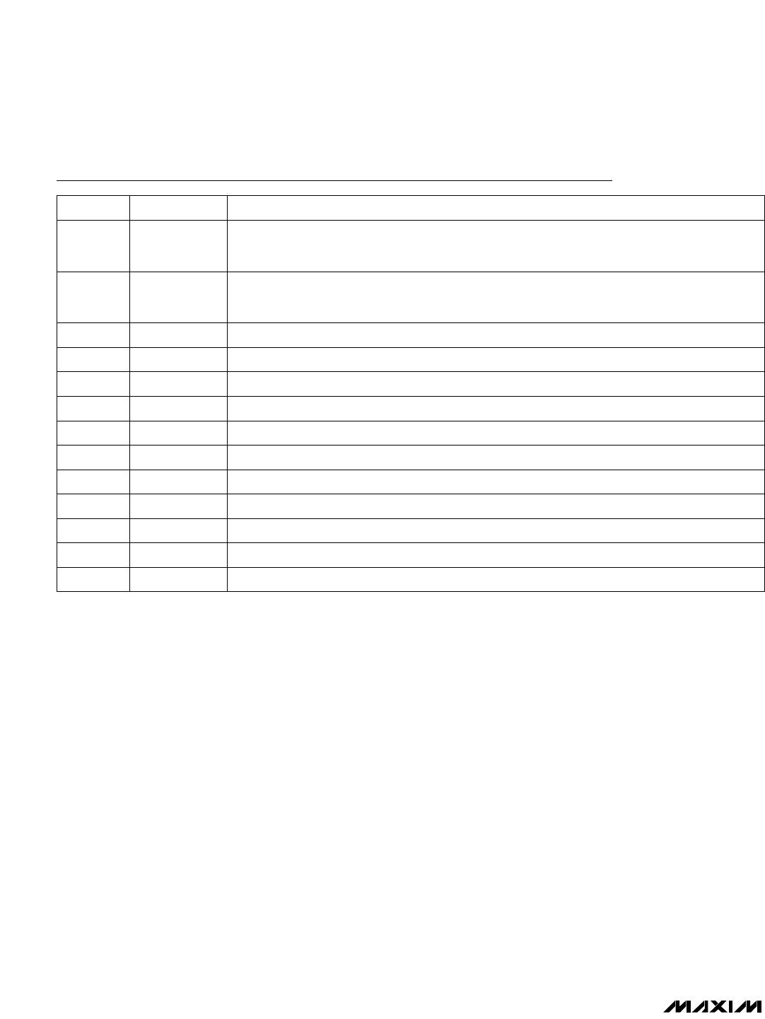
Pin Description
NAME FUNCTION
1, 47, 48 A2, A0, A1
Address Inputs. The input of a 3-to-8 decoder, which controls channel selection for all four 1-to-8
multiplexers simultaneously. Selects which output channels are connected to the input during
sample mode (Tables 1, 2).
2–5 M0–M3
Mode-Selection/Multiplexer-Enable Inputs 0 to 3. Independent controls for each of the four 1-to-8
multiplexers. A logic low enables sample mode by connecting the selected channel (via address
inputs A2, A1, A0) to IN. A logic high selects hold mode (Tables 1, 2).
PIN
6 VL Positive Digital Logic Power-Supply Input
7 DGND Digital Ground
8 V
SS
Negative Analog Power-Supply Input
9 AGND Analog Ground
10 IN Analog Input. Connects to the input of all four internal 1-to-8 multiplexers.
11 CH Clamp High Input. Clamps V
OUT
to (V
CH
+ 0.7V).
12 CL Clamp Low Input. Clamps V
OUT
to (V
CL
- 0.7V).
13 N.C. No Connection. Not internally connected.
14–29 OUT0–OUT15 Sample/Hold Outputs 0 to 15
30 V
DD
Positive Analog Power-Supply Input
31–46 OUT16–OUT31 Sample/Hold Outputs 16 to 31