RCL e3
Vishay Draloric
Document Number: 20046 For technical questions, contact: thickfilmchip@vishay.com
www.vishay.com
Revision: 14-Jun-11 269
Long Side Termination Thick Film Chip Resistors
This document is subject to change without notice.
THE PRODUCTS DESCRIBED HEREIN AND THIS DOCUMENT ARE SUBJECT TO SPECIFIC DISCLAIMERS, SET FORTH AT www.vishay.com/doc?91000
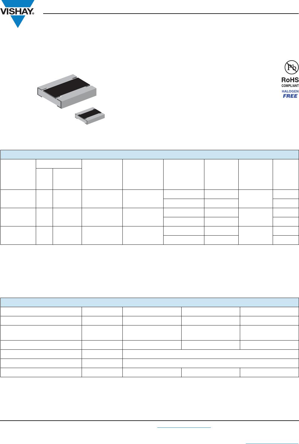
FEATURES
Enhanced power rating
Long side terminations
Pure tin solder contacts on Ni barrier layer,
provides compatibility with lead (Pb)-free and
lead containing soldering processes
Compliant to RoHS Directive 2002/95/EC
Halogen-free according to IEC 61249-2-21 definition
AEC-Q200 qualified
Notes
These resistors do not feature a limited lifetime when operated within the permissible limits. However, resistance value drift increasing over
operating time may result in exceeding a limit acceptable to the specific application, thereby establishing a functional lifetime.
Marking: See datasheet “Surface Mount Resistor Marking” (document number 20020).
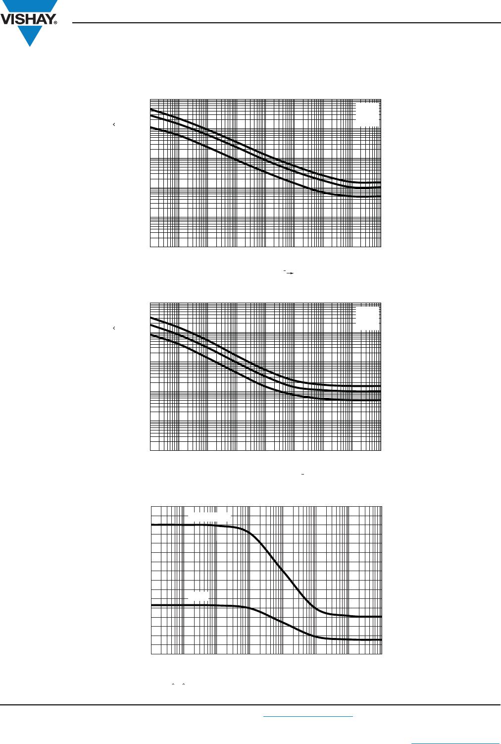
Power rating depends on the max. temperature at the solder point, the component placement density and the substrate material.
(1)
Specified power rating requires dedicated mounting conditions to achieve the required thermal resistance.
Notes
(2)
The power dissipation on the resistors generates a temperature rise against the local ambient, depending on the heat flow support of the
printed-circuit board (thermal resistance). The rated dissipation applies only if the permitted film temperature of 155 °C is not exceeded.
(3)
Specified power rating requires dedicated mounting conditions to achieve the required thermal resistance.
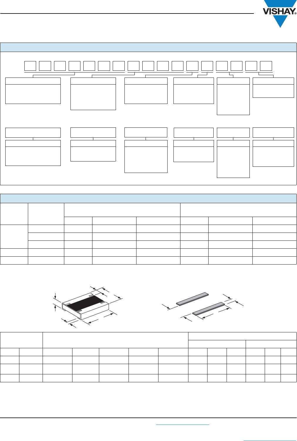
STANDARD ELECTRICAL SPECIFICATIONS
MODEL
SIZE
RATED
DISSIPATION
P
70
W
LIMITING
ELEMENT
VOLTAGE
U
max.
AC/DC
V
TEMPERATURE
COEFFICIENT
ppm/K
TOLERANCE
%
RESISTANCE
RANGE
SERIES
INCH METRIC
RCL0612 e3 0612 RR 1632M 0.5 75
± 100 ± 1
1R0 to 1M
E24; E96
± 200 ± 5 E24
RCL1218 e3 1218 RR 3246M 1.0 200
± 100 ± 1
1R0 to 2.2M
E24; E96
± 200 ± 5 E24
RCL1225 e3 1225 RR 3263M
2.0
(1)
200
± 100 ± 1
1R0 to 1M
E24; E96
± 200 ± 5 E24
TECHNICAL SPECIFICATIONS
DESCRIPTION UNIT RCL0612 RCL1218 RCL1225
Rated Dissipation P
70
(2)
W0.5 1.0 2.0
(3)
Limiting Element Voltage
U
max.
AC/DC
V 75 200 200
Insulation Voltage U
ins
(1 min) V > 100 > 300 > 300
Insulation Resistance > 10
9
Category Temperature Range °C - 55 to + 155
Weight mg 11 29.5 55