BAT60JFILM

1/5
BAT60J
®
January 2003 - Ed: 6A
SMALL SIGNAL SCHOTTKY DIODE
VERY SMALL CONDUCTION LOSSES
NEGLIGIBLE SWITCHING LOSSES
LOW FORWARD VOLTAGE DROP
EXTREMELY FAST SWITCHING
SURFACE MOUNTED DEVICE
FEATURES AND BENEFITS
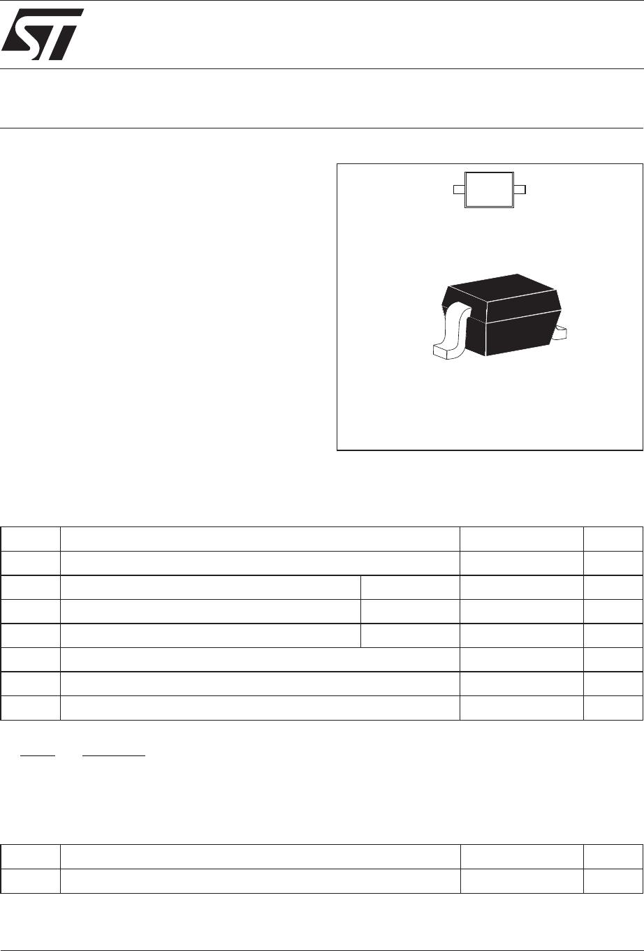
Schottky barrier diode encapsulated in a SOD-323
small SMD package.
This device is intended for use in portable
equipments. It is suited for DC to DC converters,
step-up conversion and power management.
DESCRIPTION
SOD-323
Symbol Parameter Value Unit
V
RRM
Repetitive peak reverse voltage 10 V
I
F
Peak forward current δ = 0.11 3 A
I
FSM
Surge non repetitive forward current tp=10ms 5 A
P
tot
Power Dissipation Ta=25°C 310 mW
T
stg
Storage temperature range - 65 to +150 °C
Tj Maximum operating junction temperature * 150 °C
TL Maximum temperature for soldering during 10s 260 °C
ABSOLUTE RATINGS (limiting values)
Symbol Parameter Value Unit
R
th (j-a)
Junction to ambient (*) 400 °C/W
(*) Mounted on epoxy board with recommended pad layout.
THERMAL RESISTANCE
*:
dPtot
dTj Rth j a
<
1
()
thermal runaway condition for a diode on its own heatsink
A
K
60
BAT60J
2/5
Symbol Tests Conditions Tests conditions Min. Typ. Max. Unit
V
F
* Forward voltage drop Tj = 25°C I
F
= 10 mA 0.28 0.32 V
I
F
= 100 mA 0.35 0.40
I
F
= 1 A 0.53 0.58
I
R
** Reverse leakage current Tj = 25°C V
R
=5V 1 3 µA
Tj = 25°C V
R
= 8 V 1.3 4
Tj = 25°C V
R
=10V 2 6
Tj = 25°C V
R
= 12 V 2.5 7.5
Tj = 80°C V
R
= 8 V 73 150
STATIC ELECTRICAL CHARACTERISTICS
Pulse test: * tp = 380µs, δ <2%
** tp = 5ms, δ <2%
To evaluate the conduction losses the following equation:
P=0.38xI
F(AV)
+ 0.17 I
F
2
(RMS)
BAT60J
3/5
0.0 0.1 0.2 0.3 0.4 0.5 0.6 0.7
0.00
0.05
0.10
0.15
0.20
0.25
0.30
0.35
IF(av) (A)
PF(av)(W)
T
δ
=tp/T
tp
δ = 0.05
δ = 0.1
δ = 0.2
δ = 0.5
δ = 1
Fig. 1: Average forward power dissipation versus
average forward current.
0 25 50 75 100 125 150
0.0
0.4
0.8
1.2
1.6
2.0
2.4
2.8
3.2
Tamb(°C)
IF(A)
T
δ
=tp/T
tp
Fig. 2-1: Peak forward current versus ambient
temperature (δ = 0.11).
0 25 50 75 100 125 150
0.00
0.05
0.10
0.15
0.20
0.25
0.30
0.35
0.40
0.45
0.50
0.55
0.60
Tamb(°C)
IF(av)(A)
T
δ
=tp/T
tp
Fig. 2-2: Average forward current versus ambient
temperature (δ = 0.5).
1E-3 1E-2 1E-1 1E+0
0.0
0.5
1.0
1.5
2.0
2.5
3.0
t(s)
IM(A)
Ta=25°C
Ta=50°C
Ta=75°C
IM
t
δ=0.5
Fig. 3: Non repetitive surge peak forward current
versus overload duration (maximum values).
1E-4 1E-3 1E-2 1E-1 1E+0 1E+1 1E+2
1E-3
1E-2
1E-1
1E+0
t(s)
Zth(j-a)/Rth(j-a)
δ = 0.5
δ = 0.2
δ = 0.1
Single pulse
T
δ
=tp/T
tp
Fig. 4: Relative variation of thermal impedance junc-
tion to ambient versus pulse duration (Epoxy printed
circuit board FR4 with recommended pad layout).
012345678910
1E-4
1E-3
1E-2
1E-1
1E+0
1E+1
VR(V)
IR(mA)
Tj=80°C
Tj=25°C
Tj=150°C
Fig. 5: Reverse leackage current versus reverse
voltage applied (typical values).

BAT60JFILM

Mfr. #:
Manufacturer:
STMicroelectronics
Description:
Schottky Diodes & Rectifiers 3.0 Amp 10 Volt
Lifecycle:
New from this manufacturer.
Delivery:
DHL FedEx Ups TNT EMS
Payment:
T/T Paypal Visa MoneyGram Western Union

Products related to this Datasheet