Characteristics T4 series
4/15 DocID7699 Rev 9
Figure 1. Maximum power dissipation versus
RMS on-state current (full cycle)
Figure 2. RMS on-state current versus case
temperature (full cycle)
0.0 0.5 1.0 1.5 2.0 2.5 3.0 3.5 4.0
0
1
2
3
4
5
6
P(W)
I (A)
T(RMS)
72$%'3$.,3$.
7
&
&

 

,
7506
$









 
Figure 3. RMS on-state current versus ambient
temperature (printed circuit board FR4, copper
thickness: 35µm) (full cycle)
Figure 4. Relative variation of thermal
impedance versus pulse duration
 











7
D
&
,
7506
$
'3$.6 FPð
W
S
V
(
. >=
WK
5
WK
@
5
WKMD
'3$.,3$.
72$%'3$.,3$.
5
WKMF
(
(
(
(
(
(
(
(
Figure 5. On-state characteristics
(maximum values)
Figure 6. Surge peak on-state current versus
number of cycles
0.0 0.5 1.0 1.5 2.0 2.5 3.0 3.5 4.0 4.5 5.0
0.1
1.0
10.0
30.0
I (A)
TM
V (V)
TM
T max.
V = 0.90V
R = 120 m
j
to
d
Ω
T=
j
T max.
j
T = 25°C
j
.
1 10 100 1000
0
5
10
15
20
25
30
35
I (A)
TSM
Number of cycles
t=20ms
One cycle
Non repetitive
T initial=25°C
j
Repetitive
T =110°C
C
DocID7699 Rev 9 5/15
T4 series Characteristics
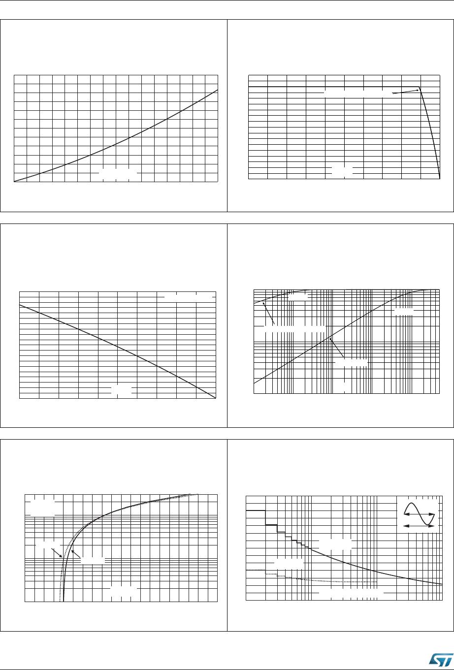
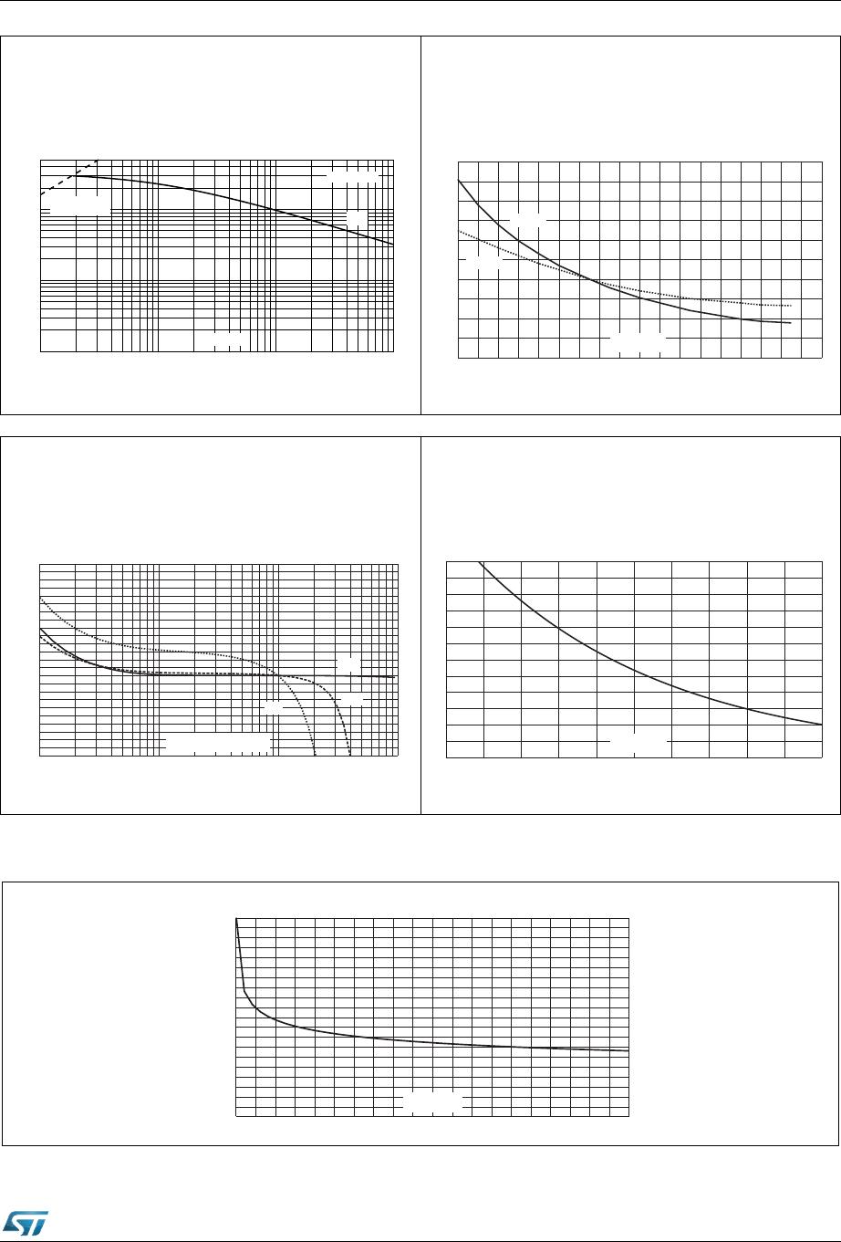
Figure 7. Non-repetitive surge peak on-state
current for a sinusoidal pulse
with width t
p
< 10 ms
Figure 8. Relative variation of gate trigger
current, holding current and latching current
versus junction temperature (typical values)




 

W
S
PV
,
760
$
,
760
7
M
LQLWLDO &
GOGWOLPLWDWLRQ
$V
-40 -20 0 20 40 60 80 100 120 140
0.0
0.5
1.0
1.5
2.0
2.5
T (°C)
j
I,I,I[T] /
GTHL j
I ,I ,I [T =25°C]
GTHL j
I
GT
I
H
& I
L
Figure 9. Relative variation of critical rate of
decrease of main current versus (dV/dt)c
(typical values)
Figure 10. Relative variation of critical rate of
decrease of main current versus junction
temperature
Figure 11. DPAK thermal resistance junction to ambient versus copper surface under tab (printed
circuit board FR4, copper thickness: 35 µm)
0.1 1.0 10.0 100.0
0.0
0.2
0.4
0.6
0.8
1.0
1.2
1.4
1.6
1.8
2.0
2.2
2.4
(dV/dt)c (V/µs)
(dI/dt)c [(dV/dt)c] / Specified (dI/dt)c
T405
T435
T410
0 25 50 75 100 125
0
1
2
3
4
5
6
(dI/dt)c [T ] / pecified]
j
(dI/dt)c [T s
j
T (°C)
j
0 4 8 1216202428323640
0
10
20
30
40
50
60
70
80
90
100
S(cm²)
R (°C/W)
th(j-a)
Package information T4 series
6/15 DocID7699 Rev 9
2 Package information
Molding epoxy meets UL94, V0 and is halogen free
Lead-free package
Recommended torque: 0.4 to 0.6 N·m for TO-220AB
In order to meet environmental requirements, ST offers these devices in different grades of
ECOPACK
®
packages, depending on their level of environmental compliance. ECOPACK
®
specifications, grade definitions and product status are available at: www.st.com.
ECOPACK
®
is an ST trademark.
2.1 DPAK package information
Figure 12. DPAK package outline
Note: This package drawing may slightly differ from the physical package. However, all the
specified dimensions are guaranteed.

T405-600B-TR

Mfr. #:
Manufacturer:
STMicroelectronics
Description:
Triacs 4.0 Amp 600 Volt
Lifecycle:
New from this manufacturer.
Delivery:
DHL FedEx Ups TNT EMS
Payment:
T/T Paypal Visa MoneyGram Western Union