TC7106/A/TC7107/A
DS21455D-page 12 © 2008 Microchip Technology Inc.
6.0 DIGITAL SECTION (TC7107A)
Figure 6-2 shows a TC7106A block diagram. It is
designed to drive common anode LEDs. It is identical
to the TC7106A, except that the regulated supply and
backplane drive have been eliminated and the segment
drive is typically 8 mA. The 1000’s output (Pin 19) sinks
current from two LED segments, and has a 16 mA drive
capability.
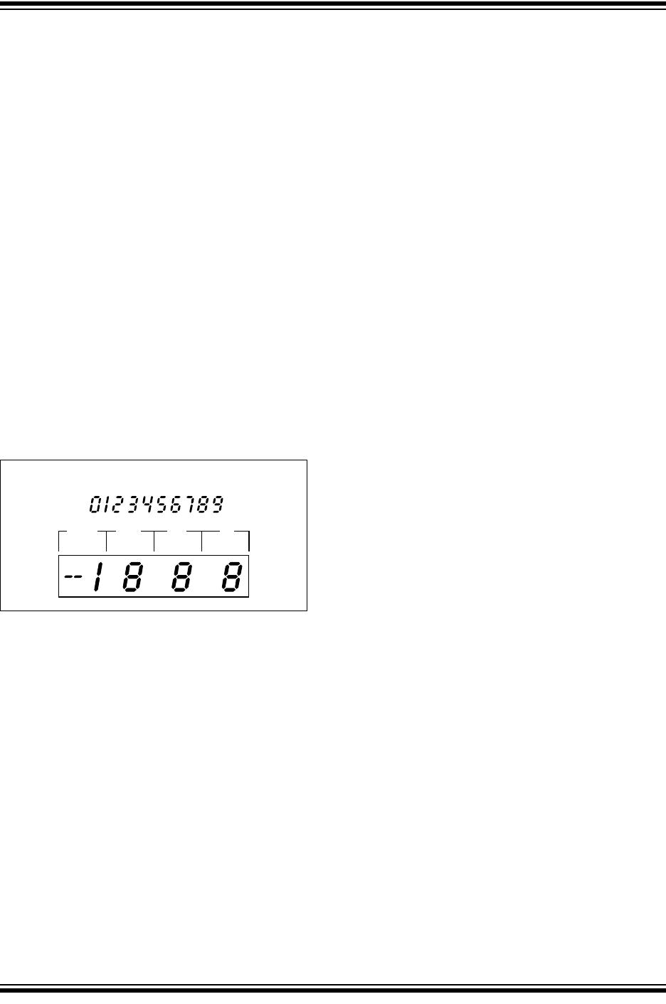
In both devices, the polarity indication is “ON” for
negative analog inputs. If V
IN
- and V
IN
+ are reversed,
this indication can be reversed also, if desired.
The display font is the same as the TC7106A.
6.1 System Timing
The oscillator frequency is divided by 4 prior to clocking
the internal decade counters. The four-phase
measurement cycle takes a total of 4000 counts, or
16,000 clock pulses. The 4000-count cycle is indepen-
dent of input signal magnitude.
Each phase of the measurement cycle has the
following length:
1. Auto-zero phase: 1000 to 3000 counts (4000 to
12000 clock pulses).
For signals less than full scale, the auto-zero phase is
assigned the unused reference integrate time period:
2. Signal integrate: 1000 counts (4000 clock
pulses).
This time period is fixed. The integration period is:
EQUATION 6-1:
3. Reference Integrate: 0 to 2000 counts (0 to 8000
clock pulses).
The TC7106A/TC7107A are drop-in replacements for
the TC7106/TC7107 parts. External component value
changes are not required to benefit from the low drift
internal reference.
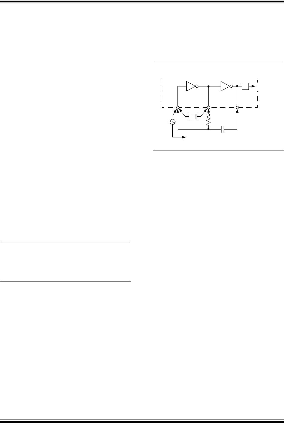
6.2 Clock Circuit
Three clocking methods may be used (see Figure 6-1):
1. An external oscillator connected to Pin 40.
2. A crystal between Pins 39 and 40.
3. An RC oscillator using all three pins.
FIGURE 6-1: Clock Circuits.
Where:
F
OSC
= Externally set clock frequency
T
SI
4
F
OSC
-------------
1000
×
=
TC7106A
TC7107A
4
Crystal
RC Network
40
38
EXT
OSC
39
µ
To TEST Pin on TSC7106A
To GND Pin on TSC7107A
To
Counter