UEI-12/4.2-Q12P-C

www.murata-ps.com
www.murata-ps.com/support
For full details go to
www.murata-ps.com/rohs
 
UEI Series
50-60W Isolated Wide-Range DC/DC Converters
MDC_UEI Series 50-60W.C10 Page 1 of 14
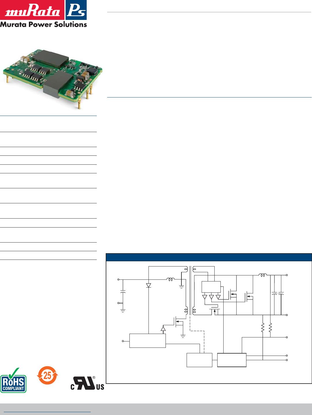
SIMPLIFIED SCHEMATIC
Featuring a full 50-60 Watt output in 2.9 square inches of board area,
the UEI series isolated DC/DC converter family offers efficient
regulated DC power for printed circuit board mounting.
GATE
DRIVE
OPTO
ISOLATION
Control
Reference, trim &
Error Amplifier
+V
IN
+V
OUT
–V
OUT
–V
IN
On/Off
Control
TRIM
–SENSE
+SENSE
ISOLATION
BARRIER
Typical topology is shown.
Typical unit
Wide range 4:1 inputs on the 1.50" x 1.90" x
0.38" converter are either 9 to 36 Volts DC (Q12
models) or 18 to 75 Volts DC (Q48 models), ideal
for battery-powered and telecom equipment.
Fixed output voltages from 3.3 VDC to 15 VDC are
regulated to within ±0.05% and may be trimmed
within ±10% of nominal output. Applications
include small instruments, computer-based
systems, data communications equipment, remote
sensor systems, vehicle and portable electronics.
The UEI 50-60W Series includes full magnetic
and optical isolation up to 2250 Volts DC (basic
insulation). For connection to digital systems, the
outputs offer fast settling to current step loads
and tolerance of higher capacitive loads. Excellent
ripple and noise specifi cations assure compatibil-
ity to circuits using CPU’s, ASIC’s, programmable
logic and FPGAs. No minimum load is required.
For systems requiring controlled startup/shut-
down, an external switch, transistor or digital logic
may be used to activate the remote On/Off control.
Remote Sense inputs compensate for resistive line
drops at high currents.
A wealth of self-protection features avoid both
converter and external circuit problems. These
include input undervoltage lockout, input overvolt-
age and overtemperature shutdown. The outputs
current limit using the “hiccup” autorestart
technique and the outputs may be short-circuited
indefi nitely. Additional features include output
overvoltage and reverse conduction elimination.
The synchronous rectifi er forward topology offers
high effi ciency for minimal heat buildup and “no
fan” operation.
PRODUCT OVERVIEW
FEATURES
Small footprint DC/DC converter, ideal for high
current applications
Industry standard 1.50˝ x 1.90˝ x 0.38˝ open
frame package and pinout
Wide range input voltages 9-36 and 18-75Vdc
Assembly and attachment for RoHS standards
Isolation up to 2250 VDC (basic)
Up to 50-60W total output power with
overtemperature shutdown
High effi ciency synchronous rectifi er forward
topology
Stable no-load operation with no required
external components
–40 to +85°C temperature range with derating
Certifi ed to UL60950-1, CSA-C22.2 No. 234,
EN60950-1, 2nd Edition safety approvals
Extensive self-protection shut down features
RoHS-6 compliant
Figure 1. Simplifi ed block diagram
www.murata-ps.com/support
PART NUMBER STRUCTURE
UEI Series
50-60W Isolated Wide-Range DC/DC Converters
MDC_UEI Series 50-60W.C10 Page 2 of 14
Unipolar Wide Input
These are partial model numbers. Please refer to the full model number structure for complete
ordering part numbers.
Sense input is not included for 12 V
OUT and higher models. Sense is optional for 5 VOUT and lower.
All specifi cations are typical at nominal line voltage and full load, +25 deg.C. unless otherwise
noted. See detailed specifi cations.
Output capacitors are 1 μF ceramic || 10 μF electrolytic. Input cap is 22 μF, low ESR.
I/O caps are necessary for our test equipment and may not be needed for your application.
Maximum Rated Output
Current in Amps
Nominal Output Voltage
UEI -
/
Q12-3.3
15
Input Voltage Range:
Q12 = 9-36V
Q48 = 18-75V
C
RoHS-6 Hazardous Substance Compliance
(does not claim EU RoHS exemption 7b–lead in solder)
-P R
Sense Inputs (5 VOUT and lower):
R = Sense included as standard (for 5 VOUT and lower models only. 12 VOUT and higher
models do not offer the sense option.)
Blank = Sense not installed for 5 VOUT and lower models. Pins 5 and 8 omitted.
PERFORMANCE SPECIFICATIONS SUMMARY AND ORDERING GUIDE
Root Model
Output Input
Effi ciency
Sense
Input
Package
VOUT
(V)
IOUT
(A)
Power R/N (mVp-p) Regulation (Max.)
VIN
Nom.
(V)
Range
(V)
IIN,
no load
(mA)
IIN, full
load (A)
(W) Typ. Max. Line Load
Min. Typ.
Case Pinout
UEI-3.3/15-Q12PR-C 3.3 15.0 49.5 15 30 ±0.05% ±0.06% 24 9-36 130 2.33 86.8% 88.5% yes C74 P52
UEI-3.3/18-Q48NR-C 3.3 18.0 59.4 60 125 ±0.075% ±0.2% 48 18-75 130 1.38 87% 89.5% yes C74 P52
UEI-5/10-Q12PR-C 5 10.0 50.0 35 50 ±0.1% ±0.1% 24 9-36 130 2.31 89% 90% yes C74 P52
UEI-5/12-Q48NR-C 5 12.0 60.0 70 100 ±0.1% ±0.15% 48 18-75 130 1.37 89.5% 91% yes C74 P52
UEI-12/4.2-Q12P-C 12 4.2 50.4 50 120 ±0.05% ±0.05% 24 9-36 130 2.35 87.8% 89.5% no C74 P51
UEI-12/5-Q48N-C 12 5.0 60.0 40 70 ±0.2% ±0.2% 48 18-75 130 1.42 87% 89.8% no C74 P51
UEI-15/3.3-Q12P-C 15 3.3 49.5 30 100 ±0.075% ±0.05% 24 9-36 130 2.29 88.3% 90% no C74 P51
UEI-15/4-Q48N-C 15 4.0 60.0 35 60 ±0.075% ±0.05% 48 18-75 50 1.40 87.5% 89.3% no C74 P51
On/Off Control Logic:
P = Positive
N = Negative
Lx
Pin Length Option
Blank = standard pin length 0.25 in. (6.35 mm)
L1 = 0.110 in. (2.79 mm)*
L2 = 0.145 in. (3.68 mm)*
*Minimum order quantity is required. Samples available with standard pin length only.
Note:
Some model number combinations may not be available. See website or contact your local Murata sales representative.
H
Conformal Coating Option
Blank = No coating, standard
H = Coating added, optional
(built to order; contact Murata Power Solutions for MOQ and lead times.)*
Positive “P” logic is standard for Q12 models and optional special
order for Q48 models. Negative “N” logic is standard for Q48
models and optional special order for Q12 models.
www.murata-ps.com/support
UEI Series
50-60W Isolated Wide-Range DC/DC Converters
MDC_UEI Series 50-60W.C10 Page 3 of 14
INPUT CHARACTERISTICS
Model Family
V
IN
Start-up
threshold
Under-
voltage
Shut-
down
Refl ected
(back)
Ripple
Current
2
Input Current
Recom-
mended
Fuse
Internal
Input
Filter
Type
Reverse
Polarity
Protection
Remote On/Off Control
Inrush
Tran-
sient
Output
Short
Circuit
Low
Line
Standby
Mode
On/Off
Current
Positive Logic Negative Logic
V
V V mA pk-pk A
2
sec mA A mA A mA “P” model suffi x “N” model suffi x
UEI-3.3/15-Q12
24
9.5 8.5
30
0.05 50
6.25
1
12
L-C
None
- see
notes
1
OFF=Gnd pin or
–0.7 to +1.2V
max. ON=open
pin or +10 to
+15V max.
OFF=open pin
or +10 to +15V
max. ON=Gnd
pin or –0.7 to
+1.2V max.
UEI-3.3/18-Q48 48 17.3 16.0 3.71 6
UEI-5/10-Q12 24 9.5 8.25 6.21 12
UEI-5/12-Q48 48 17.3 16.0* 3.70 6
UEI-12/4.2-Q12 24 9.5 8.5 6.31 10
UEI-12/5-Q48 48 17.5 16.7 3.88 6
UEI-15/3.3-Q12 24 9.5 8.5 45 6.15 9
UEI-15/4-Q48 48 17.2 16.3 30 3.77 6
OUTPUT CHARACTERISTICS
Model Family
IOUT
Max.
V
OUT
Accuracy
Adjustment
Range
Temperature
Coeffi cient
Remote Sense
Compensation
Capacitive Loading Max.
Overvoltage
protection
Minimum
loading
OV
protection
method
Ripple/Noise
(20 MHz
bandwidth)
8
Line/Load
Regulation
Effi ciency
50% Load Low ESR, resistive load
Hiccup auto-start
after fault removal
A % of V
NOM % of VNOM % of VOUT /ºC % of VOUT max. µF V
UEI-3.3/15-Q12 15
±2
±10 ±0.02
+5
2,000
3.9
No
mini-
mum
load
Magnetic
feedback
See ordering guide
UEI-3.3/18-Q48 18
±1
+5 3.9
UEI-5/10-Q12 10 +5 5.9
UEI-5/12-Q48 12 +5 6.4
UEI-12/4.2-Q12 4.2
Not Available
16.5
UEI-12/5-Q48 5 16
UEI-15/3.3-Q12 3.3 24
UEI-15/4-Q48 4 21.5
*At 50% load
ABSOLUTE MAXIMUM RATINGS
Input Voltage
Q12 models
Volts, max. continuous 0-36 VDC to rated specifi cations
Volts, transient, 100 mSec
50 VDC, no damage
Q48 models
Volts, max. continuous
0-75 VDC to rated specifi cations
Volts, transient, 100 mSec 100 VDC, no damage
On/Off control, referred to –Vin -0.7 V. min to +15V max.
Input Reverse Polarity Protection See fuse section
Output Overvoltage V
OUT nom. +20% max.
Output Current
Current-limited. Devices can
withstand sustained short circuit
without damage. The outputs are
not intended to accept appreci-
able reverse current.
Overtemperature Protection
Device includes electronic over-
temperature shutdown protection
under normal operation.
Storage Temperature
-55 to +125° C.
Lead Temperature See soldering specifi cations
Absolute Maximum Ratings
Absolute maximums are stress ratings. Exposure of devices to
greater than any of these conditions may adversely affect long-term
reliability. Proper operation under conditions other than those listed
in the Performance/Functional Specifi cations Table is not implied nor
recommended.
Maximum Ratings Notes
The UEI-50/60W series does not include electronic Input Overvoltage
Protection. Therefore it is possible for the input to exceed the con-
tinuous ratings listed above and still operate. However, units are not
routinely Production-tested above the continuous ratings. Therefore,
the rated specifi cations do not apply at excessive input voltage and
performance is undetermined.
The transient specifi cations indicate that sample lots were suc-
cessfully tested for 100 mS at the transient stress voltage and were
not damaged. As a practical matter in your application, it is often
diffi cult to determine how long an input overvoltage was applied.
Therefore, do not exceed the continuous voltage rating.
FUNCTIONAL SPECIFICATIONS

UEI-12/4.2-Q12P-C

Mfr. #:
Manufacturer:
Description:
Isolated DC/DC Converters 24Vin 12Vout 4.2A 50.4W Pos polarity
Lifecycle:
New from this manufacturer.
Delivery:
DHL FedEx Ups TNT EMS
Payment:
T/T Paypal Visa MoneyGram Western Union