www.murata-ps.com/support
UEI Series
50-60W Isolated Wide-Range DC/DC Converters
MDC_UEI Series 50-60W.C10 Page 13 of 14
Remote Sense Input
Sense inputs compensate for output voltage inaccuracy delivered at the load.
This is done by correcting voltage drops along the output wiring such as mod-
erate IR drops and the current carrying capacity of PC board etch. Sense inputs
also improve the stability of the converter and load system by optimizing the
control loop phase margin.
Note: The Sense input and power Vout lines are internally connected through
low value resistors to their respective polarities so that the converter can
operate without external connection to the Sense. Nevertheless, if the Sense
function is not used for remote regulation, the user should connect +Sense to
+V
OUT and –Sense to –VOUT at the converter pins.
The remote Sense lines carry very little current. They are also capacitively
coupled to the output lines and therefore are in the feedback control loop to
regulate and stabilize the output. As such, they are not low impedance inputs
and must be treated with care in PC board layouts. Sense lines on the PCB
should run adjacent to DC signals, preferably Ground. In cables and discrete
wiring, use twisted pair, shielded tubing or similar techniques.
Please observe Sense inputs tolerance to avoid improper operation:
[V
OUT(+) –VOUT(-)] – [ Sense(+) – Sense(-)] ≤ 10% of VOUT
Output overvoltage protection is monitored at the output voltage pin, not the
Sense pin. Therefore excessive voltage differences between Vout and Sense
together with trim adjustment of the output can cause the overvoltage protec-
tion circuit to activate and shut down the output.
Power derating of the converter is based on the combination of maximum
output current and the highest output voltage. Therefore the designer must insure:
(V
OUT at pins) x (IOUT) ≤ (Max. rated output power)
Trimming the Output Voltage
The Trim input to the converter allows the user to adjust the output voltage over
the rated trim range (please refer to the Specifi cations). In the trim equations and
circuit diagrams that follow, trim adjustments use either a trimpot or a single
fi xed resistor connected between the Trim input and either the +Sense or –Sense
terminals. (On some converters, an external user-supplied precision DC voltage
may also be used for trimming). Trimming resistors should have a low tempera-
ture coeffi cient (±100 ppm/deg.C or less) and be mounted close to the converter.
Keep leads short. If the trim function is not used, leave the trim unconnected.
With no trim, the converter will exhibit its specifi ed output voltage accuracy.
There are two CAUTION’s to be aware for the Trim input:
CAUTION: To avoid unplanned power down cycles, do not exceed EITHER the
maximum output voltage OR the maximum output power when setting the trim.
Be particularly careful with a trimpot. If the output voltage is excessive, the
OVP circuit may inadvertantly shut down the converter. If the maximum power
is exceeded, the converter may enter current limiting. If the power is exceeded
for an extended period, the converter may overheat and encounter overtem-
perature shut down.
CAUTION: Be careful of external electrical noise. The Trim input is a senstive
input to the converter’s feedback control loop. Excessive electrical noise may
cause instability or oscillation. Keep external connections short to the Trim
input. Use shielding if needed.
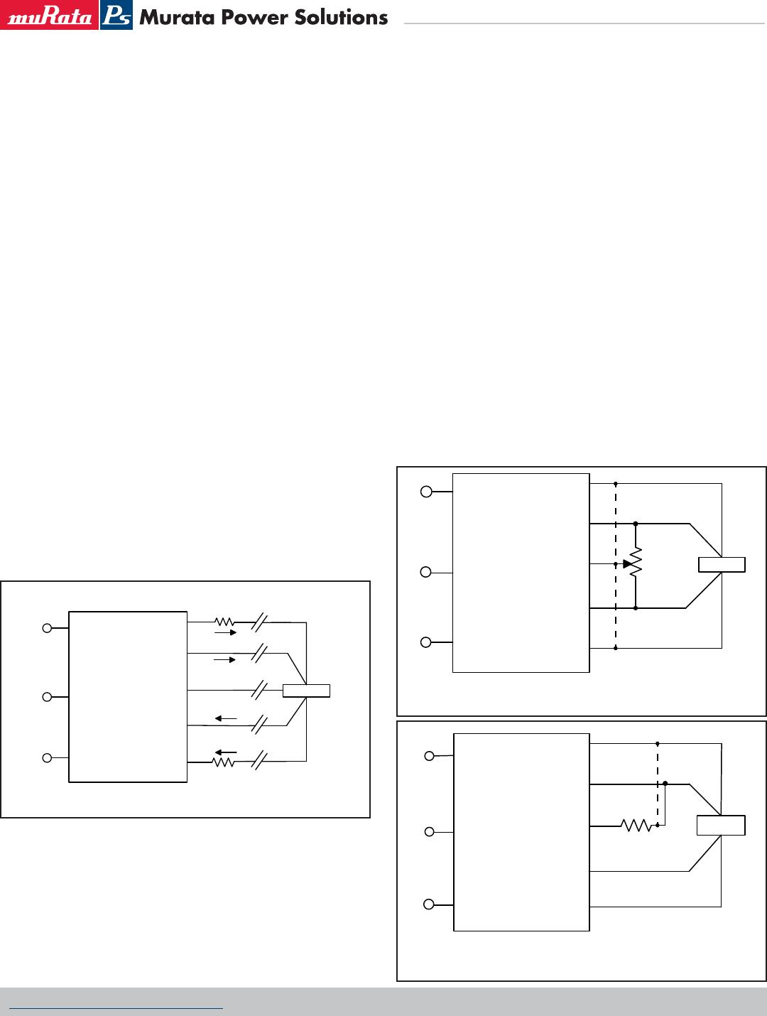
Figure 4. Remote Sense Circuit Confi guration
LOAD
Contact and PCB resistance
losses due to IR drops
Contact and PCB resistance
losses due to IR drops
+VOUT
+SENSE
TRIM
−
SENSE
-VOUT
+
VIN
ON/OFF
CONTROL
−
VIN
Sense Current
I OUT
Sense Return
I OUT Return
Figure 5. Trim adjustments using a trimpot; if sense is omitted,
connect trim pin to either +output or -output.
LOAD
7
5-22
TURNS
+VOUT
+SENSE
TRIM
−
SENSE
−
VOUT
+
VIN
ON/OFF
CONTROL
−
VIN
Figure 6. Trim adjustments to decrease Output Voltage using a Fixed Resistor;
if sense is omitted, connect trim pin to +output.
LOAD
R TRIM DOWN
+VOUT
+SENSE
TRIM
−
SENSE
−
VOUT
+
VIN
ON/OFF
CONTROL
−
VIN
