TC74HC4049AFTEL

TC74HC4049,4050AP/AF/AFT
2014-03-01
1
TOSHIBA CMOS Digital Integrated Circuit Silicon Monolithic
TC74HC4049AP, TC74HC4049AF, TC74HC4049AFT
TC74HC4050AP, TC74HC4050AF, TC74HC4050AFT
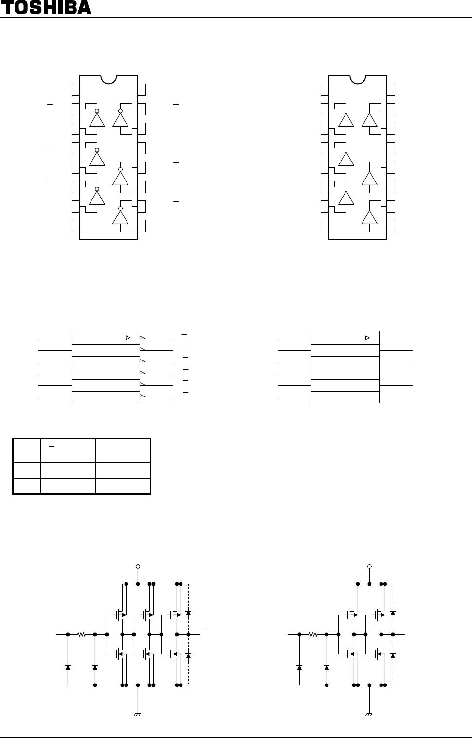
TC74HC4049AP/AF/AFT Hex
Buffer/Converter
(inverting)
TC74HC4050AP/AF/AFT Hex
Buffer/Converter
The TC74HC4049A and TC74HC4050A are high speed CMOS
HEX BUFFERs fabricated with silicon gate C
2
MOS technology.
They achieve the high speed operation similar to equivalent
LSTTL while maintaining the CMOS low power dissipation.
The TC74HC4049A is an inverting buffer, while the
TC74HC4050A is a non-inverting buffer. The internal circuits are
composed of 3-stages (HC4049A) or 2-stages (HC4050A) of
invertaers, which provided high noise immunity and stable
output.
Input protection circuits are different from those of other high
speed CMOS IC’s. They eliminate the diodes on the V
CC
side
thus providing of logic-level conversion from high-level volages
up to 15 V to low-level voltages.
They are useful for battery back up circuits, because input
voltage can be applied on IC’s which are not biased by V
CC
.
Features
High speed: t
pd
= 9 ns (typ.) at V
CC
= 5 V
Low power dissipation: I
CC
= 1 μA (max) at Ta = 25°C
High noise immunity: V
NIH
= V
NIL
= 28% V
CC
(min)
Output Drive Capability: 15 LSTTL loads
Symmetrical output impedance: |I
OH
| = I
OL
= 6 mA (min)
Balanced propagation delays: t
pLH
t
pHL
Wide operating voltage range: V
CC (opr)
= 2 V to 6 V
Pin and function compatible with 4049B/4050B
TC74HC4049AP, TC74HC4050AP
TC74HC4049AF, TC74HC4050AF
TC74HC4049AFT, TC74HC4050AFT
Weight
DIP16-P-300-2.54A : 1.00 g (typ.)
SOP16-P-300-1.27A : 0.18 g (typ.)
TSSOP16-P-0044-0.65A : 0.06 g (typ.)
Start of commercial production
1986-05
TC74HC4049,4050AP/AF/AFT
2014-03-01
2
Pin Assignment
NC: No connection
IEC Logic Symbol
Truth Table
A Y (4049A) Y (4050A)
L H L
H L H
Input and Output Equivalent Circuit
TC74HC4049A TC74HC4050A
NC
12
NC
5Y
5A 11
10
9
16
1
2
3
4
5
6
7
3Y
3A
GND
1Y
4Y
8
6A
15
4A
6Y
2Y
2A
14 1A
13
(top view)
TC74HC4050A
V
CC
(top view)
TC74HC4049A
GND
3A
Y3
2A
Y2
1A
Y1
V
CC
1
2
3
4
5
6
7
8
16
15
14
13
12
11
10
9
NC
Y6
6A
NC
Y5
5A
Y4
4A
(3)
(7)
(5)
2A
4A
3A
(9)
(2)
(6)
Y2
Y4
(4)
(10)
Y3
1
Y1
1A
TC74HC4049A
(11)
6A
5A
(14)
(12)
Y6
(15)
Y5
(3)
(7)
(5)
2A
4A
3A
(9)
(2)
(6)
2Y
4Y
(4)
(10)
3Y
1
1Y
1A
TC74HC4050A
(11)
6A
5A
(14)
(12)
6Y
(15)
5Y
Y
V
CC
GND
A
V
CC
GND
A
Y
TC74HC4049,4050AP/AF/AFT
2014-03-01
3
Absolute Maximum Ratings (Note 1)
Characteristics Symbol Rating Unit
Supply voltage range V
CC
0.5 to 7 V
DC input voltage V
IN
0.5 to 18 (Note 2) V
DC output voltage V
OUT
0.5 to V
CC
+ 0.5 V
Input diode current I
IK
20 mA
Output diode current I
OK
±20 mA
DC output current I
OUT
±35 mA
DC V
CC
/ground current I
CC
±75 mA
Power dissipation P
D
500 (DIP) (Note 3)/180 (SOP/TSSOP) mW
Storage temperature T
stg
65 to 150 °C
Note 1: Exceeding any of the absolute maximum ratings, even briefly, lead to deterioration in IC performance or
even destruction.
Using continuously under heavy loads (e.g. the application of high temperature/current/voltage and the
significant change in temperature, etc.) may cause this product to decrease in the reliability significantly
even if the operating conditions (i.e. operating temperature/current/voltage, etc.) are within the absolute
maximum ratings and the operating ranges.
Please design the appropriate reliability upon reviewing the Toshiba Semiconductor Reliability Handbook
(“Handling Precautions”/“Derating Concept and Methods”) and individual reliability data (i.e. reliability test
report and estimated failure rate, etc).
Note 2: DC input voltage (V
IN
) specified is measured to GND and is not related to V
CC
.
Recommended operating range is 0 V to 15 V and it is possible to convert logic-levels from 15 V to 5 V or 5
V to 2 V.
Note 3: 500 mW in the range of Ta = 40 to 65°C. From Ta = 65 to 85°C a derating factor of 10 mW/°C shall be
applied until 300 mW.
Operating Ranges (Note)
Characteristics Symbol Rating Unit
Supply voltage V
CC
2 to 6 V
Input voltage V
IN
0 to 15
V
Output voltage V
OUT
0 to V
CC
V
Operating temperature T
opr
40 to 85 °C
Input rise and fall time t
r
, t
f
0 to 1000 (V
CC
= 2.0 V)
0 to 500 (V
CC
= 4.5 V)
0 to 400 (V
CC
= 6.0 V)
ns
Note: The operating ranges must be maintained to ensure the normal operation of the device.
Unused inputs must be tied to either V
CC
or GND.

TC74HC4049AFTEL

Mfr. #:
Manufacturer:
Toshiba
Description:
Inverters CMOS Logic IC 9ns 6mA 2.0 to 6.0V
Lifecycle:
New from this manufacturer.
Delivery:
DHL FedEx Ups TNT EMS
Payment:
T/T Paypal Visa MoneyGram Western Union