KMA199E All information provided in this document is subject to legal disclaimers. © NXP B.V. 2011. All rights reserved.
Product data sheet Rev. 2 — 7 December 2011 17 of 32
NXP Semiconductors
KMA199E
Programmable angle sensor
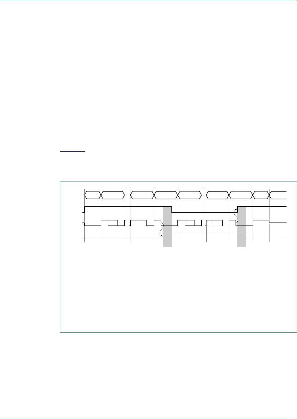
13.3.2 Read access
In order to read data from the sensor, the following procedure must be done:
• Start condition: The master drives a rising edge after a LOW level
• Command: The master sends a read command, that is the last bit is set
• Handover: The master sends a handover bit, that is a logic 0 and disables his output
after a three-quarter bit period
• Takeover: The slave drives a LOW level after the falling edge for t
tko(slv)
• Data: The slave sends two data bytes
• Handover: The slave sends a handover bit, that is a logic 0 and disables his output
after a three-quarter bit period
• Takeover: The master drives a LOW level after the falling edge for t
tko(mas)
• Stop condition: The master drives a rising edge after a LOW level
Figure 14
shows the read access of the digital interface. The signal OWI represents the
data on the bus, which is either caused by the master or by the slave. The signals master
output enable and slave output enable just symbolize if the master or the slave output is
enabled or disabled respectively.
(1) Duration of LOW level for slave takeover t
tko(slv)
.
(2) There is an overlap in the output enables of master and slave, because both drive a LOW
level. However this ensures the independency from having a pull-up or pull-down on the bus.
In addition it improves the ElectroMagnetic Compatibility (EMC) robustness, because all levels
are actively driven.
(3) Duration of LOW level for master takeover t
tko(mas)
.
(4) If the master does not take the bus and a pull-up exists, the stop condition is generated by the
pull-up. Otherwise a time-out is generated if there is a pull-down and the slave waits for a rising
edge as start condition.
(5) If the master might not drive the bus, the bus is defined by the bus-pull.
Fig 14. OWI read access
001aag744
master
output
enable
slave
output
enable
START CMD7 CMD0 RDATA0
(1)
(2) (2) (4)
(5)
(3)
HANDSHAKE HANDSHAKERDATA15 IDLESTOP
OWI

