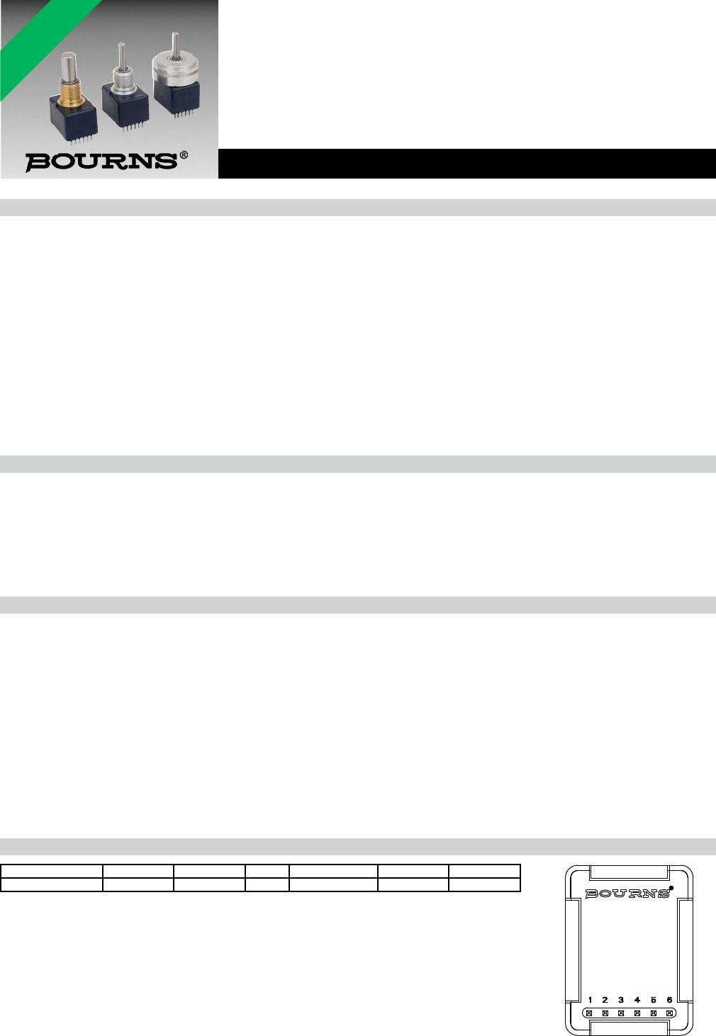
Features
■ 3.3 and 5 VDC voltage supply option
■ PWM Absolute Position
■ Bushing or servo mount
■ Non-contacting magnetic technology
■ Small size
■ CMOS and TTL compatible
■ Resolution: 1024 states
■ Long life
■ High operating speed
■ Highly repeatable
■ Sealed option
■ Magnetic technology
EMS22P - Non-Contacting PWM Encoder
*RoHS Directive 2002/95/EC Jan. 27, 2003 including annex and RoHS Recast 2011/65/EU June 8, 2011.
Specifi cations are subject to change without notice.
The device characteristics and parameters in this data sheet can and do vary in different applications and actual device
performance may vary over time.
Users should verify actual device performance in their specifi c applications.
Electrical Characteristics
Resolution ................................................................................................................................................................................................................ 1024 states
Insulation Resistance (500 VDC) ......................................................................................................................................................................1,000 megohms
Electrical Travel ........................................................................................................................................................................................................ Continuous
Supply Voltage ........................................................................................................................................................................5.0 VDC ±10 %, 3.3 VDC ±10 %
Supply Current .................................................................................................................................................................................................20 mA maximum
Output Voltage
Low Output Level ................................................................................................................................................................................. Vss+0.4 V maximum
High Output Level...................................................................................................................................................................................Vdd-0.5 V minimum
Output Current
With 4.5 VDC Supply Voltage .......................................................................................................................................................................4 mA maximum
With 3.0 VDC Supply Voltage .......................................................................................................................................................................2 mA maximum
Rise/Fall Time (Incremental Output) ............................................................................................................................................................... 500 ns maximum
Shaft RPM (Ball Bearing) .........................................................................................................................................................................10,000 rpm maximum
Linearity ..............................................................................................................................................................................................................................0.5 %
Accuracy
Nominal ..........................................................................................................................................................................................................±0.7 ° or better
Worst Case ................................................................................................................................................................................................................... ±1.4 °
Output Transition Noise ................................................................................................................................................................................... 0.12 ° RMS max.
Environmental Characteristics
Operating Temperature Range ........................................................................................................................................ -40 ºC to +125 ºC (-40 °F to +257 °F)
Storage Temperature Range ........................................................................................................................................... -55 °C to +125 °C (-67 °F to +257 °F)
Humidity ....................................................................................................................................................................MIL-STD-202, Method 103B, Condition B
Vibration ..............................................................................................................................................................................................................................15 G
Shock ..................................................................................................................................................................................................................................50 G
Rotational Life
S Bushing (@1,000 rpm) ................................................................................................................................................................. 100,000,000 revolutions
T & W Bushings (@1,000 rpm with 250 g side load) ........................................................................................................................ 50,000,000 revolutions
IP Rating ............................................................................................................................................................................................................................. IP 65
Mechanical Characteristics
Mechanical Angle ............................................................................................................................................................................................ 360 ° Continuous
Torque
Starting .................................................................................................................................................................................... 43 ±21 g-cm (0.6 ±0.3 oz-in.)
Running ................................................................................................................................................................................... 29 ±14 g-cm (0.4 ±0.2 oz-in.)
Mounting Torque .........................................................................................................................................................................................203 N-cm (18 lb.-in.)
Shaft End Play ...................................................................................................................................................................... 0.30 mm (0.012 ”) T.I.R. maximum
Shaft Radial Play ..................................................................................................................................................................0.12 mm (0.005 ”) T.I.R. maximum
Weight ..............................................................................................................................................................................................................11 gms. (0.4 oz.)
Terminals ......................................................................................................................................................................................... Axial, radial or ribbon cable
Soldering Condition
Manual Soldering .................................................................................................................... 96.5Sn/3.0Ag/0.5Cu solid wire or no-clean rosin cored wire
370 °C (700 °F) max. for 3 seconds
Wave Soldering ............................................................................................................................................. 96.5Sn/3.0Ag/0.5Cu solder with no-clean fl ux
260 °C (500 °F) max. for 10 seconds
Wash processes .......................................................................................................................................................................................Not recommended
Marking ....................................................................................................................................Manufacturer’s trademark, name, part number, and date code.
Hardware ....................................................................One lockwasher and one mounting nut supplied with each encoder, except on servo mount versions.
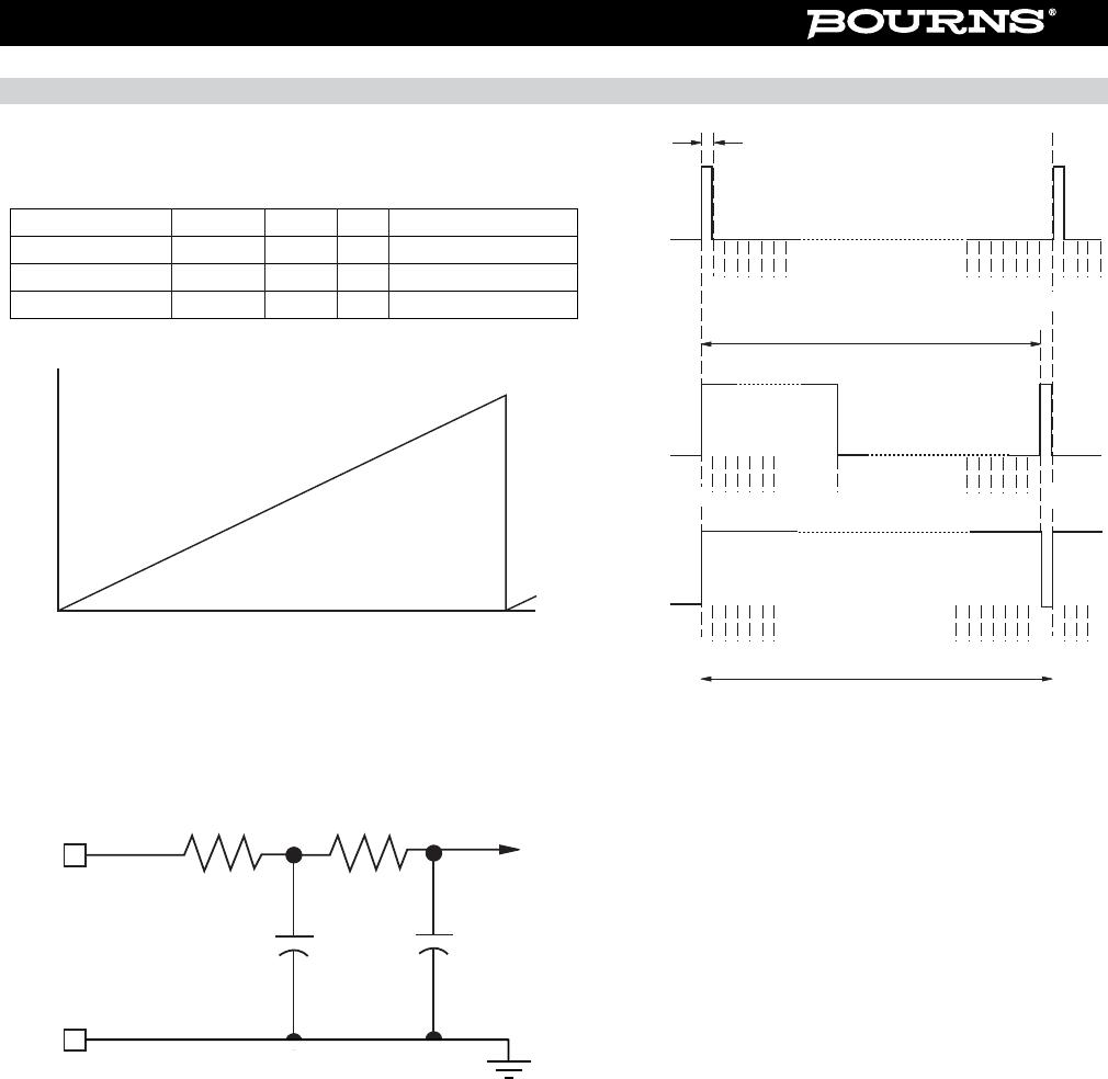
Pin Confi guration
Output Type Pin 1 Pin 2 Pin 3 Pin 4 Pin 5 Pin 6
PWM PWM Signal GND GND GND VCC* CS**
* Can be 5 or 3.3 VDC depending on the version.
** Active low chip select pin; if not used connect pin 6 to GND.