Nexperia
PMEG3005ESF
30 V, 0.5 A low VF MEGA Schottky barrier rectifier
PMEG3005ESF All information provided in this document is subject to legal disclaimers.
©
Nexperia B.V. 2017. All rights reserved
Product data sheet 10 March 2017 6 / 13
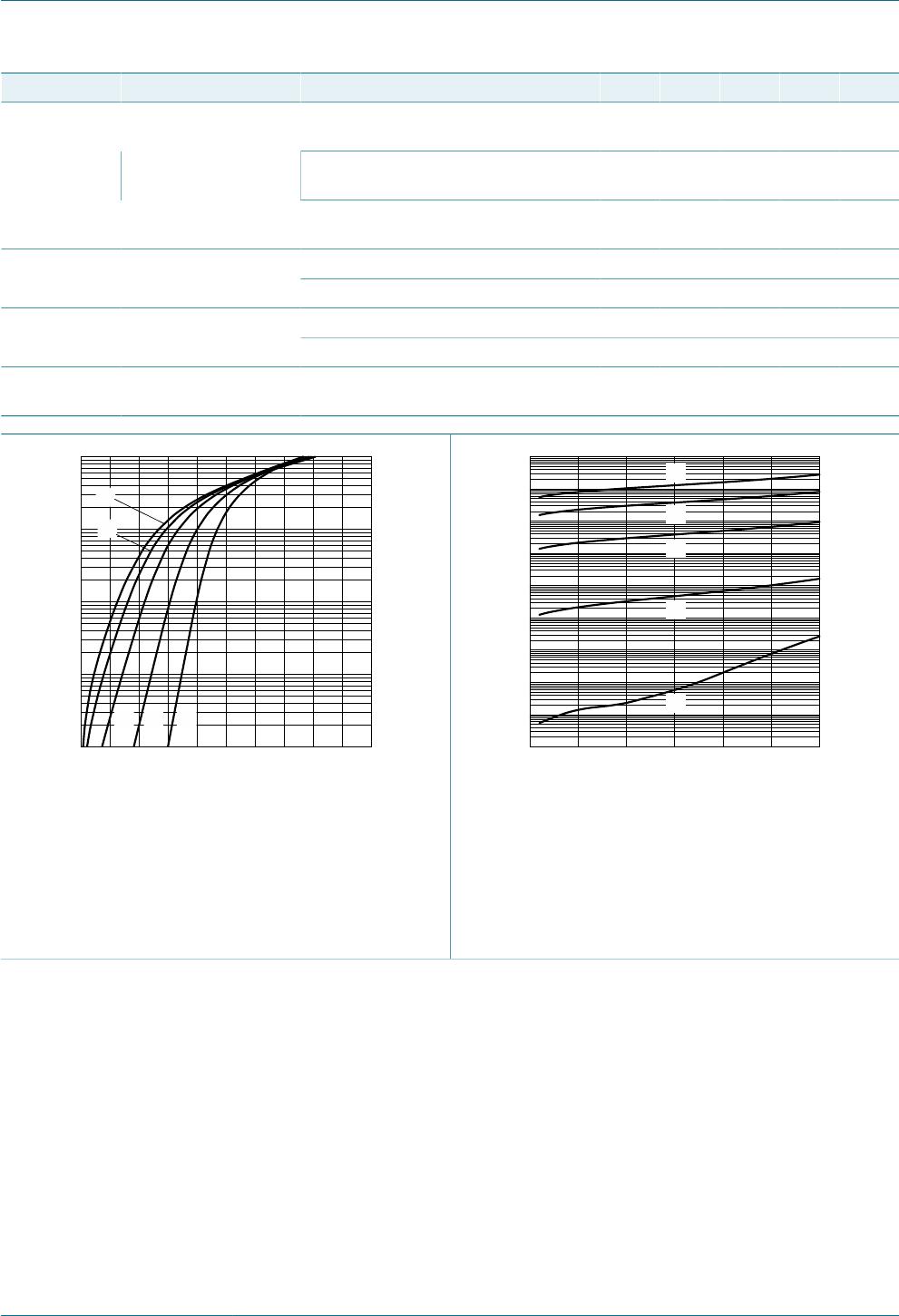
V
R
(V)
0 403010 20
aaa-011863
20
10
30
40
C
D
(P
F
)
0
f = 1 MHz; T
amb
= 25 °C
Fig. 6. Diode capacitance as a function of reverse
voltage; typical values
I
F(AV)
(A)
0 0.80.60.2 0.4
aaa-012580
0.2
0.3
0.1
0.4
0.5
P
F(AV)
(W)
0
(1)
(2)
(3)
(4)
T
j
= 150 °C
(1) δ = 0.1
(2) δ = 0.2
(3) δ = 0.5
(4) δ = 1
Fig. 7. Average forward power dissipation as a
function of average forward current; typical
values
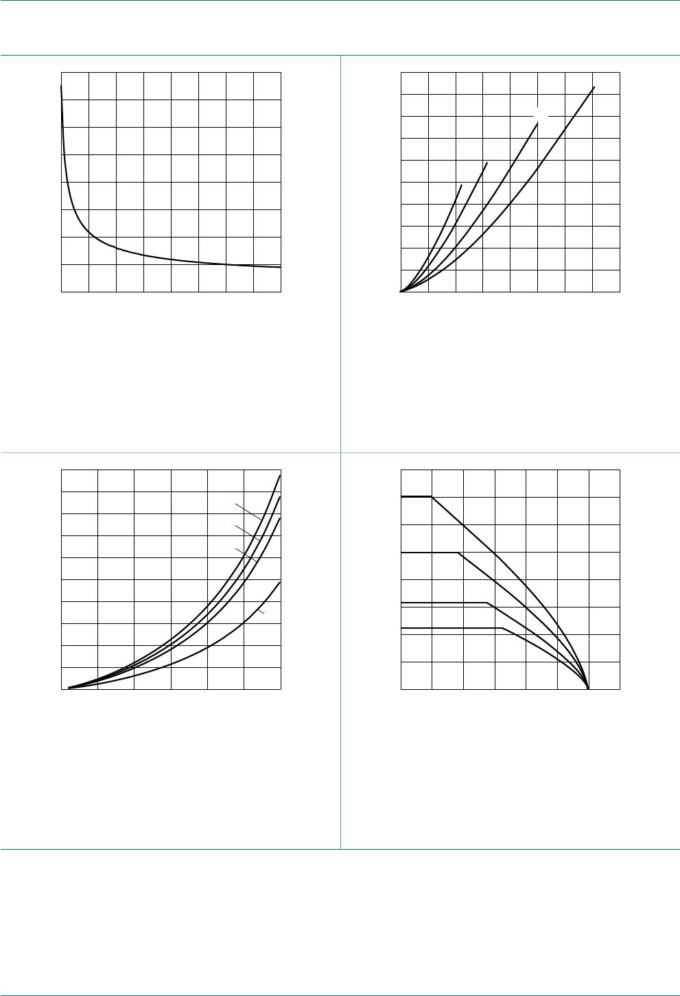
aaa-012581
V
R
(V)
0 302010
0.010
0.015
0.005
0.020
0.025
P
R(AV)
(W)
0
(3)
(4)
(2)
(1)
T
j
= 125 °C
(1) δ = 1
(2) δ = 0.9
(3) δ = 0.8
(4) δ = 0.5
Fig. 8. Average reverse power dissipation as a
function of reverse voltage; typical values
T
amb
(°C)
17512525 150100500 75
aaa-012582
0.4
0.2
0.6
0.8
I
F(AV)
(A)
0
(1)
(2)
(3)
(4)
FR4 PCB, standard footprint
T
j
= 150 °C
(1) δ = 1; DC
(2) δ = 0.5; f = 20 kHz
(3) δ = 0.2; f = 20 kHz
(4) δ = 0.1; f = 20 kHz
Fig. 9. Average forward current as a function of
ambient temperature; typical values