PMEG3020BER_1 © NXP B.V. 2009. All rights reserved.
Product data sheet Rev. 01 — 16 April 2009 3 of 13
NXP Semiconductors
PMEG3020BER
2 A low V
F
MEGA Schottky barrier rectifier
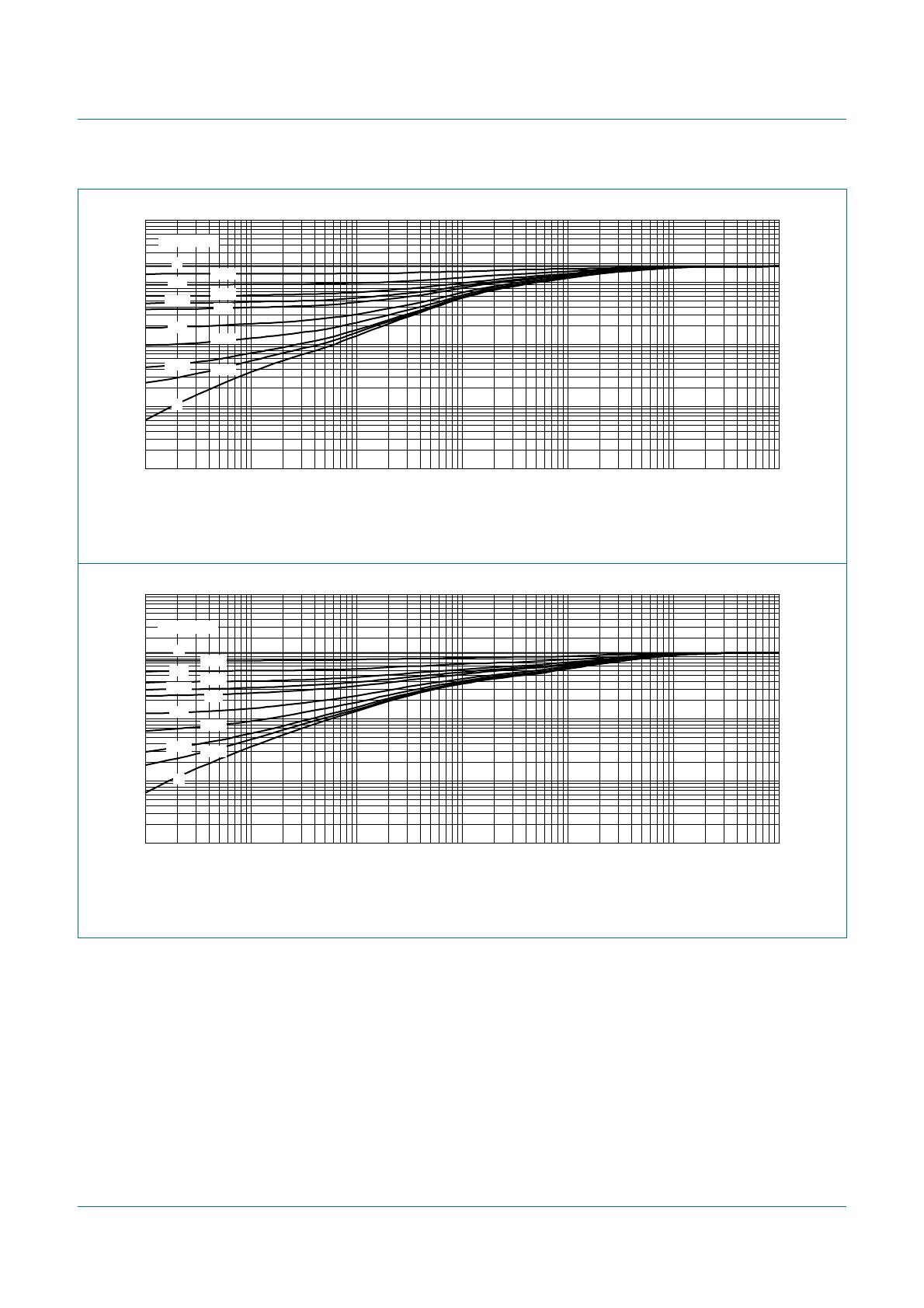
[1] Device mounted on a ceramic PCB, Al
2
O
3
, standard footprint.
[2] T
j
=25°C prior to surge.
[3] Reflow soldering is the only recommended soldering method.
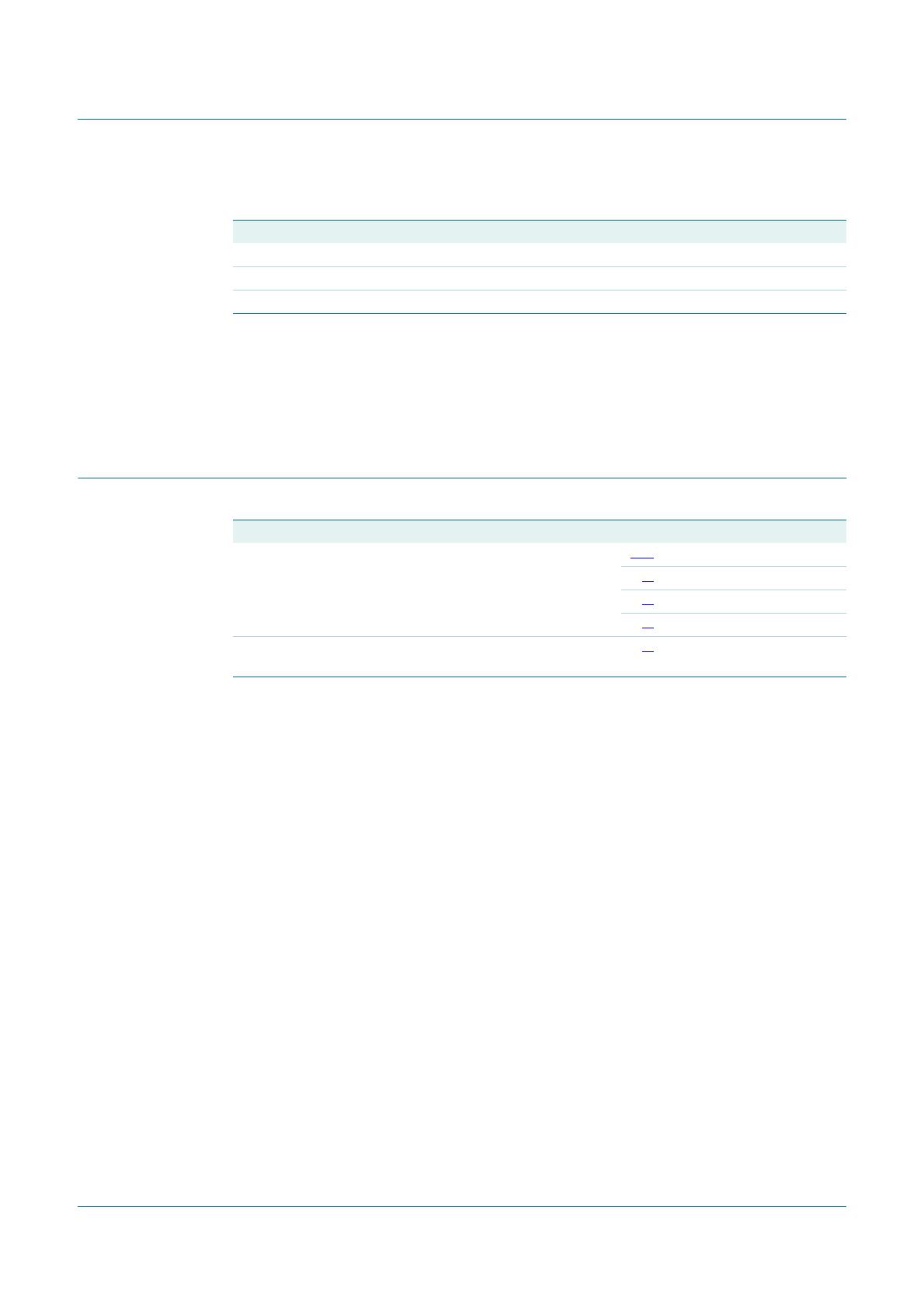
[4] Device mounted on an FR4 PCB, single-sided copper, tin-plated and standard footprint.
[5] Device mounted on an FR4 PCB, single-sided copper, tin-plated, mounting pad for cathode 1 cm
2
.
6. Thermal characteristics
[1] For Schottky barrier diodes thermal runaway has to be considered, as in some applications the reverse
power losses P
R
are a significant part of the total power losses.
[2] Reflow soldering is the only recommended soldering method.
[3] Device mounted on an FR4 PCB, single-sided copper, tin-plated and standard footprint.
[4] Device mounted on an FR4 PCB, single-sided copper, tin-plated, mounting pad for cathode 1 cm
2
.
[5] Device mounted on a ceramic PCB, Al
2
O
3
, standard footprint.
[6] Soldering point of cathode tab.
T
j
junction temperature - 150 °C
T
amb
ambient temperature 55 +150 °C
T
stg
storage temperature 65 +150 °C
Table 5. Limiting values
…continued
In accordance with the Absolute Maximum Rating System (IEC 60134).
Symbol Parameter Conditions Min Max Unit
Table 6. Thermal characteristics
Symbol Parameter Conditions Min Typ Max Unit
R
th(j-a)
thermal resistance from
junction to ambient
in free air
[1][2]
[3]
- - 220 K/W
[4]
- - 130 K/W
[5]
--70K/W
R
th(j-sp)
thermal resistance from
junction to solder point
[6]
--18K/W
PMEG3020BER_1 © NXP B.V. 2009. All rights reserved.
Product data sheet Rev. 01 — 16 April 2009 4 of 13
NXP Semiconductors
PMEG3020BER
2 A low V
F
MEGA Schottky barrier rectifier
FR4 PCB, standard footprint
Fig 1. Transient thermal impedance from junction to ambient as a function of pulse duration; typical values
FR4 PCB, mounting pad for cathode 1 cm
2
Fig 2. Transient thermal impedance from junction to ambient as a function of pulse duration; typical values
006aab362
10
1
10
2
10
3
Z
th(j-a)
(K/W)
10
1
t
p
(s)
10
3
10
2
10
3
10110
2
10
1
duty cycle =
1
0.75
0.5
0.33
0.25
0.2
0.1
0.05
0.02
0.01
0
006aab363
10
1
10
2
10
3
Z
th(j-a)
(K/W)
10
1
t
p
(s)
10
3
10
2
10
3
10110
2
10
1
duty cycle =
1
0.75
0.5
0.33
0.25
0.2
0.1
0.05
0.02
0.01
0
PMEG3020BER_1 © NXP B.V. 2009. All rights reserved.
Product data sheet Rev. 01 — 16 April 2009 5 of 13
NXP Semiconductors
PMEG3020BER
2 A low V
F
MEGA Schottky barrier rectifier
7. Characteristics
Ceramic PCB, Al
2
O
3
, standard footprint
Fig 3. Transient thermal impedance from junction to ambient as a function of pulse duration; typical values
006aab364
10
1
10
2
10
3
Z
th(j-a)
(K/W)
10
1
t
p
(s)
10
3
10
2
10
3
10110
2
10
1
duty cycle =
1
0.75
0.5
0.33
0.25
0.2
0.1
0.05
0.02
0.01
0
Table 7. Characteristics
T
j
=25
°
C unless otherwise specified.
Symbol Parameter Conditions Min Typ Max Unit
V
F
forward voltage I
F
= 0.1 A - 315 360 mV
I
F
= 0.7 A - 390 430 mV
I
F
= 1 A - 405 450 mV
I
F
= 1.5 A - 430 480 mV
I
F
= 2 A - 460 520 mV
I
R
reverse current V
R
=5V - 2 - µA
V
R
=10V - 3 - µA
V
R
=30V - 15 50 µA
C
d
diode capacitance f=1MHz
V
R
= 1 V - 170 - pF
V
R
=10V - 60 - pF

PMEG3020BER,115

Mfr. #:
Manufacturer:
Nexperia
Description:
Schottky Diodes & Rectifiers SCHOTTKY DIODE G4005CT/SOT2
Lifecycle:
New from this manufacturer.
Delivery:
DHL FedEx Ups TNT EMS
Payment:
T/T Paypal Visa MoneyGram Western Union

Products related to this Datasheet