30LVD28-R

30LV Series
www.vishay.com
Vishay Cera-Mite
Revision: 06-Jun-13
1
Document Number: 23103
For technical questions, contact: ceramitesupport@vishay.com
THIS DOCUMENT IS SUBJECT TO CHANGE WITHOUT NOTICE. THE PRODUCTS DESCRIBED HEREIN AND THIS DOCUMENT
ARE SUBJECT TO SPECIFIC DISCLAIMERS, SET FORTH AT www.vishay.com/doc?91000
AC Line Rated Disc Capacitors
Class X1, 400 V
AC
/Class Y2, 300 V
AC
INSULATION RESISTANCE
Min. 1000 F
TOLERANCE ON CAPACITANCE
± 10 %; ± 20 %
DISSIPATION FACTOR
2.0 % max. at 1 kHz; 1 V
CERAMIC DIELECTRIC
C0G, U2J, P3K, R3L (Class 1)
X7R, Y5U (Class 2)
CLIMATIC CATEGORY ACC. TO EN 60068-1
25/125/21
OPERATING TEMPERATURE RANGE
- 30 °C to + 125 °C
FEATURES
Complying with IEC 60384-14 3
rd
edition
High reliability
Complete range of capacitance values
Radial leads
Singlelayer AC Disc capacitors
Material categorization: For definitions of compliance
please see www.vishay.com/doc?99912
APPLICATIONS
X1/Y2 according to IEC 60384-14.3
Across-the-line
Line by-pass
Antenna coupling
DESIGN
The capacitors consist of a ceramic disc of which both sides
are silver-plated. Connection leads are made of tinned
copper having a diameter of 0.032" (0.81 mm) or 0.025"
(0.64 mm). The capacitors may be supplied with radial
kinked or straight leads having a lead spacing of 0.375"
(9.5 mm) or 0.250" (6.4 mm). The standard tolerance is
± 20 %. Coating is made of flame retardant epoxy resin in
accordance with “UL 94 V-0.”
CAPACITANCE RANGE
10 pF to 0.015 μF
RATED VOLTAGE
IEC 60384-14.3:
X1: 400 V
AC
, 50 Hz
Y2: 300 V
AC
, 50 Hz
DIELECTRIC STRENGTH BETWEEN LEADS
Component test:
2500 V
AC
, 50 Hz, 2 s
As repeated test admissible only once with:
2250 V
AC
, 50 Hz, 2 s
Random sampling test (destructive test):
2500 V
AC
, 50 Hz, 60 s
DIELECTRIC STRENGTH OF BODY INSULATION
2300 V
AC
, 50 Hz, 60 s (destructive test)
QUICK REFERENCE DATA
DESCRIPTION VALUE
Ceramic Class 1 2
Ceramic Dielectric
C0G,
U2J, P3K,
R3L, S3L
C0G,
U2J, P3K,
R3L, S3L
X7R,
Y5U
X7R,
Y5U
Voltage (V
AC
) 300 400 300 400
Min. Capacitance (pF) 10 100
Max. Capacitance (pF) 68 15 000
Mounting Radial
30LV Series
www.vishay.com
Vishay Cera-Mite
Revision: 06-Jun-13
2
Document Number: 23103
For technical questions, contact: ceramitesupport@vishay.com
THIS DOCUMENT IS SUBJECT TO CHANGE WITHOUT NOTICE. THE PRODUCTS DESCRIBED HEREIN AND THIS DOCUMENT
ARE SUBJECT TO SPECIFIC DISCLAIMERS, SET FORTH AT www.vishay.com/doc?91000
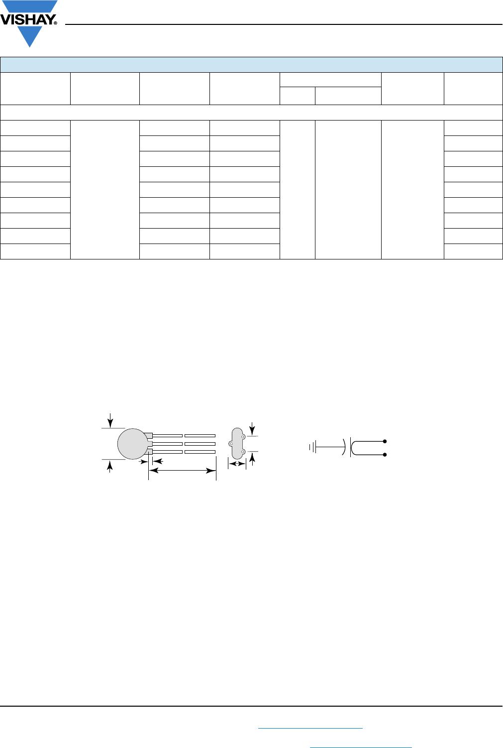
DIMENSIONS in inches (millimeters)
ORDERING INFORMATION, CERAMIC X1/Y2 CAPACITORS 30LV
C
(pF)
TOL.
(%)
D
max.
DIAMETER
INCH (mm)
T
max.
THICKNESS
INCH (mm)
WIRE SIZE LS
LEAD SPACE
INCH (mm)
ORDERING
CODE
AWG INCH (mm)
C0G
10 ± 10 0.330 (8.4) 0.190 (4.8) 22 0.025 (0.64) 0.250 (6.4) 30LVQ10-R
U2J
15 ± 10 0.330 (8.4) 0.200 (5.1) 22 0.025 (0.64) 0.250 (6.4) 30LVQ15-R
P3K
22 ± 10 0.330 (8.4) 0.185 (4.7) 22 0.025 (0.64) 0.250 (6.4) 30LVQ22-R
R3L
33 ± 10 0.330 (8.4) 0.190 (4.8) 22 0.025 (0.64) 0.250 (6.4) 30LVQ33-R
47 ± 10 0.330 (8.4) 0.170 (4.3) 22 0.025 (0.64) 0.250 (6.4) 30LVQ47-R
S3L
68 ± 10 0.330 (8.4) 0.175 (4.4) 22 0.025 (0.64) 0.250 (6.4) 30LVQ68-R
X7R
100
± 10
0.330 (8.4) 0.200 (5.1)
22 0.025 (0.64) 0.250 (6.4)
30LVT10-R
150 0.330 (8.4) 0.180 (4.6) 30LVT15-R
220 0.330 (8.4) 0.190 (4.8) 30LVT22-R
330 0.330 (8.4) 0.210 (5.3) 30LVT33-R
470 0.330 (8.4) 0.180 (4.6) 30LVT47-R
560 0.330 (8.4) 0.190 (4.8) 30LVT56-R
680 0.330 (8.4) 0.180 (4.6) 30LVTT68-R
1000 0.365 (9.3) 0.185 (4.7) 30LVTD10-R
1500 0.460 (11.7) 0.180 (4.6) 30LVTD15-R
Y5U
680
± 20
0.330 (8.4) 0.210 (5.3)
22 0.025 (0.64) 0.250 (6.4)
30LVT68-R
1000 0.330 (8.4) 0.215 (5.5) 30LVD10-R
1500 0.330 (8.4) 0.195 (5.0) 30LVD15-R
2000 0.400 (10.2) 0.210 (5.3) 30LVD20-R
2200 0.400 (10.2) 0.200 (5.1) 30LVD22-R
2700 0.430 (10.9) 0.200 (5.1) 30LVD27-R
2800 0.430 (10.9) 0.200 (5.1) 30LVD28-R
3000 0.460 (11.7) 0.200 (5.1) 30LVD30-R
3200 0.430 (10.9) 0.200 (5.1) 30LVD32-R
3300 0.460 (11.7) 0.195 (5.0) 30LVD33-R
3900 0.490 (12.4) 0.200 (5.1) 30LVD39-R
4000 0.530 (13.5) 0.210 (5.3) 30LVD40-R
0.125
max. (3.2)
Tinned Copper Leads
1.250 min.
(32)
T
max.
LS
Ø
D
max.
30LV Series
www.vishay.com
Vishay Cera-Mite
Revision: 06-Jun-13
3
Document Number: 23103
For technical questions, contact: ceramitesupport@vishay.com
THIS DOCUMENT IS SUBJECT TO CHANGE WITHOUT NOTICE. THE PRODUCTS DESCRIBED HEREIN AND THIS DOCUMENT
ARE SUBJECT TO SPECIFIC DISCLAIMERS, SET FORTH AT www.vishay.com/doc?91000
Notes
Alternate lead spacings of 7.5 mm and 10 mm are available bulk or tape and reel on request.
Minimum lead clearance according to IEC 60384-14: 0.118" (3 mm)
TAPE AND REEL OPTIONS
Part number codes and specifications for tape and reel packaging are found in the general information document - find web-link
below.
OPTIONAL 3-LEADED STYLE
An optional 3-leaded construction is available. It consists of a single capacitor with the two outside leads attached to one
electrode, and the center lead attached to the electrode. Used in feed-thru or line-to-ground applications, it allows a short
ground lead for enhanced high frequency performance.
Y5U
4700
± 20
0.620 (15.7) 0.230 (5.8)
20 0.032 (0.81) 0.375 (9.5)
30LVD47-R
5000 0.620 (15.7) 0.225 (5.7) 30LVD50-R
5500 0.560 (14.2) 0.195 (5.0) 30LVD55-R
5600 0.560 (14.2) 0.205 (5.2) 30LVD56-R
6800 0.620 (15.7) 0.215 (5.5) 30LVD68-R
8000 0.680 (17.3) 0.205 (5.2) 30LVD80-R
9000 0.720 (18.3) 0.210 (5.3) 30LVD90-R
0.010 μF 0.790 (20.1) 0.225 (5.7) 30LVS10-R
0.015 μF 0.900 (22.9) 0.210 (5.3) 30LVS15-R
ORDERING INFORMATION, CERAMIC X1/Y2 CAPACITORS 30LV
C
(pF)
TOL.
(%)
D
max.
DIAMETER
INCH (mm)
T
max.
THICKNESS
INCH (mm)
WIRE SIZE LS
LEAD SPACE
INCH (mm)
ORDERING
CODE
AWG INCH (mm)
1.250" min. (32)
4 mm max.
D
max.
T
LS
b
a
G
a
G
b
c

30LVD28-R

Mfr. #:
Manufacturer:
Description:
Ceramic Disc Capacitors 250V 20% 0.001uF
Lifecycle:
New from this manufacturer.
Delivery:
DHL FedEx Ups TNT EMS
Payment:
T/T Paypal Visa MoneyGram Western Union