6.42
9
IDT71V67703, IDT71V67903, 256K x 36, 512K x 18, 3.3V Synchronous SRAMS with
3.3V I/O, Flow-Through Outputs, Single Cycle Deselect Commercial and Industrial Temperature Ranges
1
2
3
4
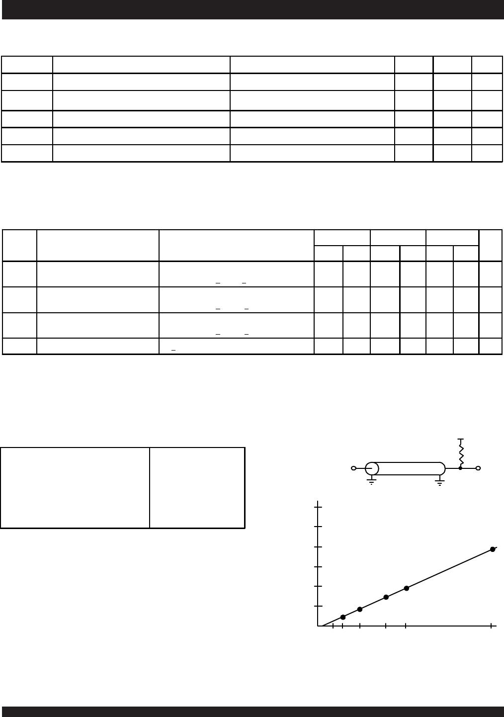
20 30 50 100 200
Δt
CD
(Typical, ns)
Capacitance (pF)
80
5
6
5309 drw 05
,
V
DDQ
/2
50Ω
I/O
Z
0
=50Ω
5309 drw 03
,
Symbol Parameter Test Conditions Min. Max. Unit
|I
LI
| Input Leakage Current V
DD
= Max., V
IN
= 0V to V
DD
___
5µA
|I
LI
|
LBO Input Leakage Current
(1)
V
DD
= Max., V
IN
= 0V to V
DD
___
30 µA
|I
LO
| Output Leakage Current V
OUT
= 0V to V
CC
___
5µA
V
OL
Output Low Voltage I
OL
= +8mA, V
DD
= Min.
___
0.4 V
V
OH
Output High Voltage I
OH
= -8mA, V
DD
= Min. 2.4
___
V
5309 tbl 08
DC Electrical Characteristics Over the Operating
Temperature and Supply Voltage Range
(1)
DC Electrical Characteristics Over the Operating
Temperature and Supply Voltage Range
(VDD = 3.3V ± 5%)
Figure 2. Lumped Capacitive Load, Typical Derating
Figure 1. AC Test Load
AC Test Load
AC Test Conditions
(VDDQ = 3.3V/2.5V)
NOTE:
1. The LBO pin will be internally pulled to V
DD if it is not actively driven in the application and the ZZ in will be internally pulled to VSS if not actively driven.
NOTES:
1. All values are maximum guaranteed values.
2. At f = f
MAX, inputs are cycling at the maximum frequency of read cycles of 1/tCYC while ADSC = LOW; f=0 means no input lines are changing.
3. For I/Os VHD = VDDQ - 0.2V, VLD = 0.2V. For other inputs VHD = VDD - 0.2V, VLD = 0.2V.
Symbol Parameter Test Conditions
7.5ns 8ns 8.5ns
Unit
Com'l Ind Com'l Ind Com'l Ind
I
DD
Operating Power Supply Current Device Selected, Outputs Open, V
DD
= Max.,
V
DDQ
= Max., V
IN
> V
IH
or < V
IL
, f = f
MAX
(2 )
265 285 210 230 190 210
mA
I
SB1
CMOS Standby Power Supply Current Device Deselected, Outputs Open, V
DD
= Max.,
V
DDQ
= Max., V
IN
> V
HD
or < V
LD
, f = 0
(2,3)
50 70 50 70 50 70
mA
I
SB2
Clock Running Power Supply Current Device Deselected, Outputs Open, V
DD
= Max.,
V
DDQ
= Max., V
IN
> V
HD
or < V
LD
, f = f
MAX
(2,.3)
145 165 140 160 135 155
mA
I
ZZ
Full Sleep Mode Supply Current ZZ > V
HD,
V
DD
= Max. 50 70 50 70 50 70 mA
5309 tbl 09
Input Pulse Levels
Input Rise/Fall Times
Input Timing Reference Levels
Output Timing Reference Levels
AC Test Load
0 to
3V
2ns
1.5V
1.5V
See Figure 1
5309 tbl 10