048 RML
www.vishay.com
Vishay BCcomponents
Revision: 28-Feb-17
4
Document Number: 28318
For technical questions, contact: aluminumcaps1@vishay.com
THIS DOCUMENT IS SUBJECT TO CHANGE WITHOUT NOTICE. THE PRODUCTS DESCRIBED HEREIN AND THIS DOCUMENT
ARE SUBJECT TO SPECIFIC DISCLAIMERS, SET FORTH AT www.vishay.com/doc?91000
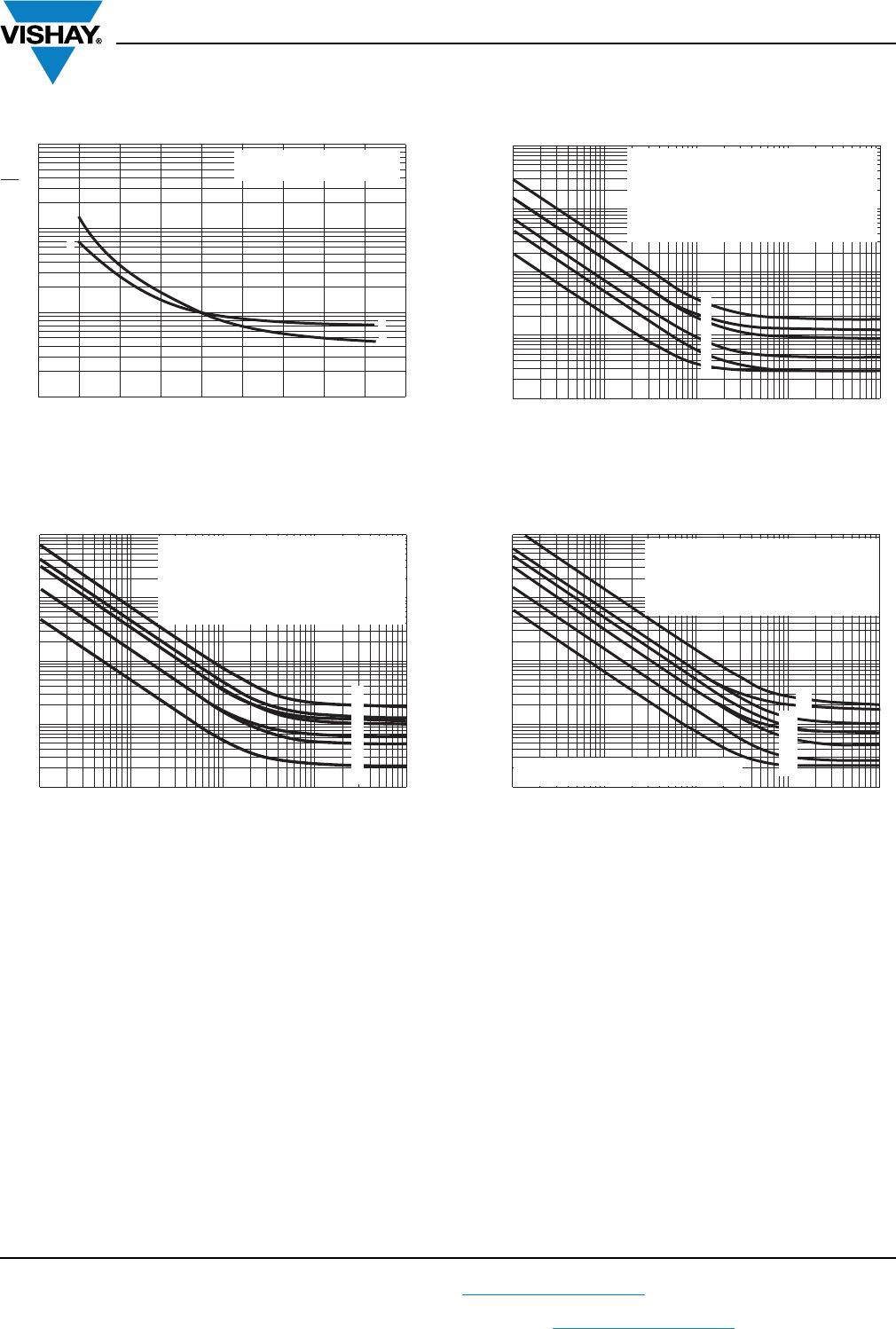
CAPACITANCE (C)
Fig. 5 - Typical multiplier of capacitance
as a function of ambient temperature
Fig. 6 - Typical multiplier of capacitance
as a function of frequency
EQUIVALENT SERIES RESISTANCE (ESR)
Fig. 7 - Typical multiplier of ESR
as a function of ambient temperature
Fig. 8 - Typical multiplier of ESR
as a function of frequency
ADDITIONAL ELECTRICAL DATA
PARAMETER CONDITIONS VALUE
Voltage
Surge voltage U
s
1.15 U
R
Reverse voltage U
rev
1 V
Current
Leakage current
After 1 min at U
R
I
L1
0.01 C
R
x U
R
+ 3 μA
After 5 min at U
R
I
L5
0.002 C
R
x U
R
+ 3 μA
Inductance
Equivalent series inductance (ESL)
Case Ø D = 10 mm Typ. 16 nH
Case Ø D 12.5 mm Typ. 18 nH
Resistance
Equivalent series resistance (ESR) Calculated from tan
max.
and C
R
(see Table 2) ESR = tan /2f C
R
- 60 - 40 - 20 0 20 40 60 80 100 120
T
amb
(20 °C)
C
0
= Capacitance at 20 °C, 100 Hz
Curve 1: 6.3 V
Curve 2: 63 V
1
2
2
1
0.8
0.9
1.0
1.1
1.2
C
0
C
C
0
= Capacitance at 20 °C, 100 Hz
1.2
1.0
0.8
0.6
0.4
0.2
0
C
0
C
5
4
3
2
1
Curve 1: 10 V
Curve 2: 16 V
Curve 3: 25 V
Curve 4: 50 V
Curve 5: 63 V
10 10
2
10
4
10
5
10
3
f (Hz)
- 60 - 40 - 20 0 20 40 60 80 100 120
T
amb
(20 °C)
C
0
= Capacitance at 20 °C, 100 Hz
1.2
1.0
0.8
0.6
0.4
0.2
0
C
0
C
3
2
1
1
2
3
Curve 1: 10 V; case Ø D = 10 mm
Curve 2: 6.3 V; case Ø D = 16 mm
Curve 3: 63 V; case Ø D = 18 mm
f (Hz)
ESR
ESR
0
ESR
0
= Typical at 20 °C, 100 Hz
2.0
1.6
1.2
0.8
0.4
0
10 10
2
10
3
10
4
10
5
1
2
3
4
5
Curve 1: 6.3 V
Curve 2: 16 V
Curve 3: 35 V
Curve 4: 50 V
Curve 5: 63 V