LT3082
8
3082f
Introduction
The LT3082 regulator is easy to use and has all the pro-
tection features expected in high performance regulators.
Included are reverse-input, reverse-output and reverse
input-to-output protection for sensitive circuitry and loads.
Additional protection includes short-circuit protection and
thermal shutdown with hysteresis.
The LT3082 fi ts well in applications needing multiple rails.
This new architecture adjusts down to zero with a single
resistor, handling modern low voltage digital IC’s as well
as allowing easy parallel operation and thermal manage-
ment without heat sinks. Adjusting to zero output allows
shutting off the powered circuitry. When the input is pre-
regulated—such as a 5V or 3.3V input supply—external
resistors can help spread the heat.
A precision “0” TC 10A reference current source connects
to the noninverting input of a power operational amplifi er.
The power operational amplifi er provides a low impedance
buffered output to the voltage on the noninverting input.
A single resistor from the noninverting input to ground
sets the output voltage. If this resistor is set to 0, zero
output voltage results. Therefore, any output voltage be-
tween zero and the maximum defi ned by the input power
supply voltage is obtainable.
The benefi t of using a true internal current source as the
reference, as opposed to a bootstrapped reference in older
regulators, is not so obvious in this architecture. A true
APPLICATIONS INFORMATION
reference current source allows the regulator to have gain
and frequency response independent of the impedance on
the positive input. On older adjustable regulators, such as
the LT1086, loop gain changes with output voltage and
bandwidth changes if the adjustment pin is bypassed
to ground. For the LT3082, loop gain is unchanged with
output voltage changes or bypassing. Output regulation
is not a fi xed percentage of output voltage, but is a fi xed
fraction of millivolts. Use of a true current source allows
all of the gain in the buffer amplifi er to provide regulation,
and none of that gain is needed to amplify up the reference
to a higher output voltage.
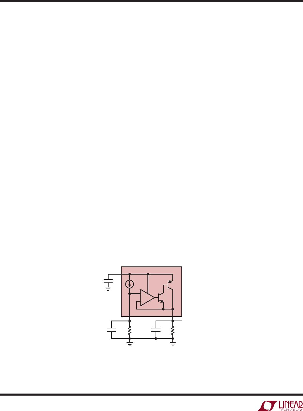
Programming Output Voltage
The LT3082 generates a 10A reference current that
fl ows out of the SET pin. Connecting a resistor from SET
to GND generates a voltage that becomes the reference
point for the error amplifi er (see Figure 1). The reference
voltage equals 10A multiplied by the value of the SET
pin resistor. Any voltage may be generated and there
is no minimum output voltage for the regulator. Table
1 lists many common output voltages and the closest
standard 1% resistor values used to generate that output
voltage.
Regulation of the output voltage requires a minimum load
current of 0.5mA. For a true 0V output operation, return
this minimum 0.5mA load current to a negative supply
voltage.
Figure 1. Basic Adjustable Regulator
3082 F01
IN
SET OUT
+
–
LT3082
10µA
R
LOAD
C
SET
R
SET
C
IN
V
OUT
= 10µA • R
SET
C
OUT