CSRF0402FT3L00

Rev Date: 03/16/2017 4 www.seielect.com
This specification may be changed at any time without prior notice marketing@seielect.com
Please confirm technical specifications before you order and/or use.
CSRF Series
Foil on Ceramic Current Sensing Chip Resistor
Stackpole Electronics, Inc.
Resistive Product Solutions
Packaging SpecificationsPaper Tape
Packaging SpecificationsEmbossed Plastic Tape
Type / Code Unit
0.028 ± 0.002 0.047 ± 0.002 0.069 ± 0.004 0.138 ± 0.002 0.315 ± 0.008 Inches
0.70 ± 0.05 1.20 ± 0.05 1.75 ± 0.10 3.50 ± 0.05 8.00 ± 0.20 mm
0.043 ± 0.004 0.075 ± 0.004 0.069 ± 0.004 0.138 ± 0.002 0.315 ± 0.008 Inches
1.10 ± 0.10 1.90 ± 0.10 1.75 ± 0.10 3.50 ± 0.05 8.00 ± 0.20 mm
0.063 ± 0.004 0.094 ± 0.004 0.069 ± 0.004 0.138 ± 0.002 0.315 ± 0.008 Inches
1.60 ± 0.10 2.40 ± 0.10 1.75 ± 0.10 3.50 ± 0.05 8.00 ± 0.20 mm
0.079 ± 0.004 0.142 ± 0.004 0.069 ± 0.004 0.138 ± 0.002 0.315 ± 0.008 Inches
2.00 ± 0.10 3.60 ± 0.10 1.75 ± 0.10 3.50 ± 0.05 8.00 ± 0.20 mm
0.079 ± 0.004 0.142 ± 0.004 0.069 ± 0.004 0.138 ± 0.002 0.315 ± 0.008 Inches
2.00 ± 0.10 3.60 ± 0.10 1.75 ± 0.10 3.50 ± 0.05 8.00 ± 0.20 mm
Type / Code Unit
0.157 ± 0.004 0.079 ± 0.004 0.079 ± 0.002 0.061 ± 0.002 0.024 ± 0.004 Inches
4.00 ± 0.10 2.00 ± 0.10 2.00 ± 0.05 1.55 ± 0.05 0.60 ± 0.10 mm
0.157 ± 0.004 0.157 ± 0.004 0.079 ± 0.002 0.061 ± 0.002 0.028 ± 0.004 Inches
4.00 ± 0.10 4.00 ± 0.10 2.00 ± 0.05 1.55 ± 0.05 0.70 ± 0.10 mm
0.157 ± 0.004 0.157 ± 0.004 0.079 ± 0.002 0.061 ± 0.002 0.038 ± 0.004 Inches
4.00 ± 0.10 4.00 ± 0.10 2.00 ± 0.05 1.55 ± 0.05 0.97 ± 0.10 mm
0.157 ± 0.004 0.157 ± 0.004 0.079 ± 0.002 0.061 ± 0.002 0.038 ± 0.004 Inches
4.00 ± 0.10 4.00 ± 0.10 2.00 ± 0.05 1.55 ± 0.05 0.97 ± 0.10 mm
0.157 ± 0.004 0.157 ± 0.004 0.079 ± 0.002 0.061 ± 0.002 0.038 ± 0.004 Inches
4.00 ± 0.10 4.00 ± 0.10 2.00 ± 0.05 1.55 ± 0.05 0.97 ± 0.10 mm
D0
T
CSRF0402
CSRF0603
CSRF0805
P0
P1
P2
CSRF1206
CSRF0612
CSRF0603
A
B
CSRF1206
CSRF0612
E
F
CSRF0402
W
CSRF0805
Type / Code Unit
0.110 ± 0.004 0.211 ± 0.004 0.069 ± 0.004 0.217 ± 0.002 0.472 ± 0.012 Inches
2.80 ± 0.10 5.35 ± 0.10 1.75 ± 0.10 5.50 ± 0.05 12.00 ± 0.30 mm
0.138 ± 0.004 0.268 ± 0.004 0.069 ± 0.004 0.217 ± 0.002 0.472 ± 0.008 Inches
3.50 ± 0.10 6.80 ± 0.10 1.75 ± 0.10 5.50 ± 0.05 12.00 ± 0.20 mm
Type / Code Unit
0.157 ± 0.004 0.157 ± 0.004 0.079 ± 0.002 0.059 ± 0.004 0.039 ± 0.008 Inches
4.00 ± 0.10 4.00 ± 0.10 2.00 ± 0.05 1.50
±
0.10 1.00 ± 0.20 mm
0.157 ± 0.002 0.157 ± 0.004 0.079 ± 0.002 0.059 ± 0.004 0.039 ± 0.008 Inches
4.00 ± 0.05 4.00 ± 0.10 2.00 ± 0.05 1.50 ± 0.10 1.00 ± 0.20 mm
CSRF2512
W
CSRF2010
A
B
CSRF2010
CSRF2512
P0
E
F
P1
P2
D0
T
Rev Date: 03/16/2017 5 www.seielect.com
This specification may be changed at any time without prior notice marketing@seielect.com
Please confirm technical specifications before you order and/or use.
CSRF Series
Foil on Ceramic Current Sensing Chip Resistor
Stackpole Electronics, Inc.
Resistive Product Solutions
Solder Land Pattern
Packaging Specifications Embossed Plastic Tape
Type / Code Unit
0.211 ± 0.004
0.462
± 0.004
0.069 ± 0.004 0.453
± 0.004 0.945 ± 0.012
0.157 ±
0.004
Inches
5.36 ±
0.10 11.74 ± 0.10 1.75
± 0.10
11.50
± 0.10
24.00
± 0.30 4.00 ± 0.10
mm
0.211
±
0.004 0.462
±
0.004 0.069 ± 0.004 0.453
±
0.004 0.945
± 0.012
0.157 ±
0.004
Inches
5.36
±
0.10 11.74 ±
0.10
1.75 ± 0.10
11.50
± 0.10
24.00 ±
0.30
4.00 ±
0.10 mm
Type / Code Unit
0.315 ± 0.004 0.079 ± 0.004 0.059 ± 0.004 0.059 ±
0.010 0.013
±
0.004 0.077 ± 0.004 Inches
8.00 ±
0.10 2.00 ±
0.10 1.50 ± 0.10 1.50 ±
0.25
0.33 ±
0.10 1.96 ± 0.10 mm
0.315
±
0.004 0.079 ± 0.004 0.059
±
0.004 0.059
± 0.010 0.013 ± 0.004 0.077 ± 0.004 Inches
8.00 ±
0.10 2.00
± 0.10 1.50 ± 0.10
1.50 ± 0.25 0.33
± 0.10 1.96
±
0.10 mm
CSRF2043
P1
P2
CSRF4320
D0
D1
T1
T2
CSRF2043
CSRF4320
W
P0
A
B
E
F
Size a b c Unit
0.008 0.031 0.024 inches
0.20 0.80 0.60
mm
0.012 0.024 0.024 inches
0.30 0.60
0.60 mm
0.020 0.020 0.024 inches
0.50 0.50 0.60 mm
0.035
0.028 0.039 inches
0.90 0.70 1.00 mm
0.047 0.047 0.055 inches
1.20 1.20 1.40 mm
0.087 0.051 0.071 inches
2.20 1.30 1.80 mm
0.024 0.051 0.142 inches
0.60 1.30 3.60 mm
0.118 0.061 0.120 inches
3.00 1.56 3.05 mm
0.150 0.083 0.134 inches
3.80 2.10 3.40 mm
0.157 0.197 0.276 inches
4.00 5.00 7.00 mm
0.118 0.079 0.472 inches
3.00 2.00 12.00 mm
CSRF0612
CSRF2010
CSRF4320
CSRF2043
CSRF0402
0.003Ω - 0.004Ω
CSRF2512
CSRF0402
0.005Ω - 0.007Ω
CSRF0402
0.008Ω - 0.05Ω
CSRF0603
CSRF1206
CSRF0805
Rev Date: 03/16/2017 6 www.seielect.com
This specification may be changed at any time without prior notice marketing@seielect.com
Please confirm technical specifications before you order and/or use.
CSRF Series
Foil on Ceramic Current Sensing Chip Resistor
Stackpole Electronics, Inc.
Resistive Product Solutions
High Power Chip Resistors and Thermal Management
Stackpole has developed several surface mount resistor series in addition to our current sense resistors,
which have had higher power ratings than standard resistor chips. This has caused some uncertainty and
even confusion by users as to how to reliably use these resistors at the higher power ratings in their designs.
The data sheets for the RHC, RMCP, RNCP, CSR, CSRN, CSRF, CSS, and CSSH state that the rated
power assumes an ambient temperature of no more than 100ºC for the CSS / CSSH series and 70ºC for all
other high power resistor series. In addition, IPC and UL best practices dictate that the combined
temperature on any resistor due to power dissipated and ambient air shall be no more than 105ºC . At first
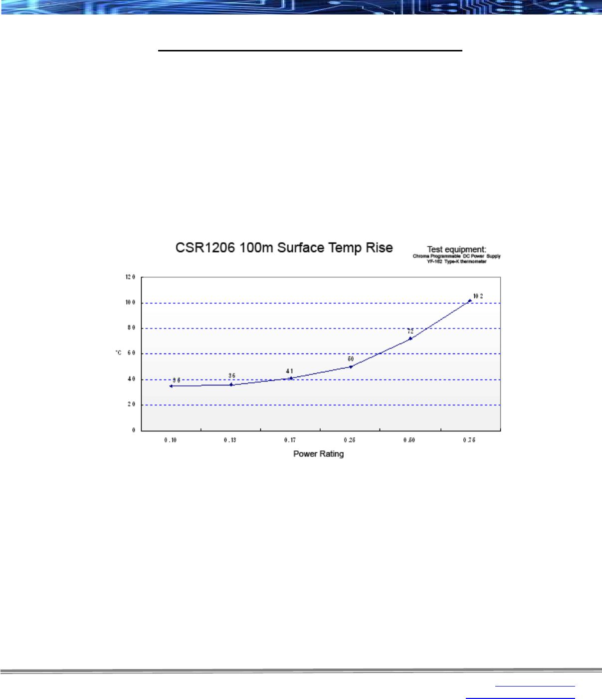
glance this wouldn’t seem too difficult, however the graph below shows typical heat rise for the CSR1206 100
milliohm at full rated power. The heat rise for the RMCP and RNCP would be similar. The RHC with its
unique materials, design, and processes would have less heat rise and therefore would be easier to
implement for any given customer.
The 102ºC heat rise shown here would indicate there will be additional thermal reduction techniques needed
to keep this part under 105ºC total hot spot temperature if this part is to be used at 0.75 watts of power.
However, this same part at the usual power rating for this size would have a heat rise of around 72ºC. This
additional heat rise may be dealt with using wider conductor traces, larger solder pads and land patterns
under the solder mask, heavier copper in the conductors, vias through PCB, air movement, and heat sinks,
among many other techniques. Because of the variety of methods customers can use to lower the effective
heat rise of the circuit, resistor manufacturers simply specify power ratings with the limitations on ambient air
temperature and total hot spot temperatures and leave the details of how to best accomplish this to the
design engineers. Design guidelines for products in various market segments can vary widely so it would be
unnecessarily constraining for a resistor manufacturer to recommend the use of any of these methods over
another.
Note: The final resistance value can be affected by the board layout and assembly process, especially the size of the
mounting pads and the amount of solder used. This is especially notable for resistance values 50 mΩ.
This should be taken into account when designing.

CSRF0402FT3L00

Mfr. #:
Manufacturer:
Description:
Foil on Ceramic Current Sensing Chip Resisto
Lifecycle:
New from this manufacturer.
Delivery:
DHL FedEx Ups TNT EMS
Payment:
T/T Paypal Visa MoneyGram Western Union