BAP64-04 All information provided in this document is subject to legal disclaimers. © NXP Semiconductors N.V. 2015. All rights reserved.
Product data sheet Rev. 5 — 28 April 2015 2 of 9
NXP Semiconductors
BAP64-04
Silicon PIN diode
4. Marking
5. Limiting values
6. Thermal characteristics
7. Characteristics
Table 3. Marking
Type number Marking Description
BAP64-04 4K* * = t : made in Malaysia
* = W : made in China
Table 4. Limiting values
In accordance with the Absolute Maximum Rating System (IEC 60134).
Values are specified per diode.
Symbol Parameter Conditions Min Max Unit
V
R
reverse voltage - 175 V
I
F
forward current - 100 mA
P
tot
total power dissipation T
sp
= 90 C- 250mW
T
stg
storage temperature 65 +150 C
T
j
junction temperature 65 +150 C
Table 5. Thermal characteristics
Symbol Parameter Conditions Typ Unit
R
th(j-sp)
thermal resistance from junction to solder point 220 K/W
Table 6. Characteristics
Values are specified per diode; T
j
= 25
C unless otherwise specified.
Symbol Parameter Conditions Min Typ Max Unit
V
F
forward voltage I
F
= 50 mA - 0.95 1.1 V
I
R
reverse current V
R
= 175 V - - 10 A
V
R
=20V - - 1 A
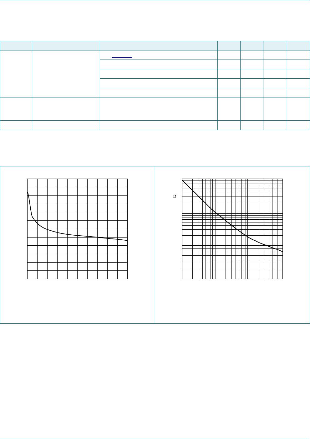
C
d
diode capacitance see Figure 1; f = 1 MHz;
V
R
= 0 V - 0.52 - pF
V
R
= 1 V - 0.37 - pF
V
R
=20V - 0.23 0.35 pF