ADA4830-1/ADA4830-2 Data Sheet
Rev. C | Page 2 of 22
TABLE OF CONTENTS
Features .............................................................................................. 1
Applications ....................................................................................... 1
General Description ......................................................................... 1
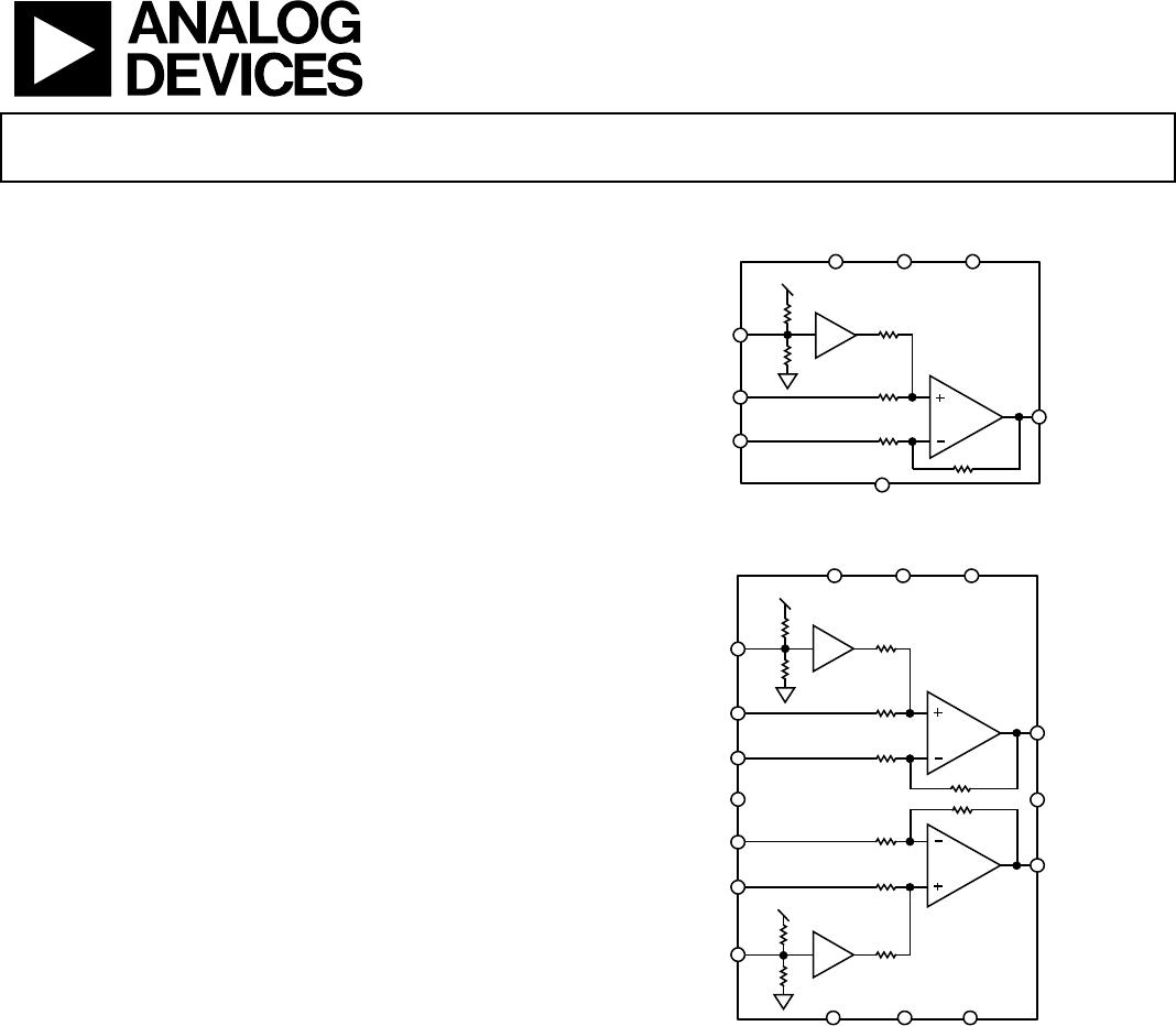
Functional Block Diagram .............................................................. 1
Revision History ............................................................................... 2
Specifications ..................................................................................... 3
5 V Operation ............................................................................... 3
3.3 V Operation ............................................................................ 4
Absolute Maximum Ratings ....................................................... 6
Thermal Resistance ...................................................................... 6
Maximum Power Dissipation ..................................................... 6
ESD Caution .................................................................................. 6
Pin Configurations and Function Descriptions ........................... 7
Typical Performance Characteristics ............................................. 9
Theory of Operation ...................................................................... 13
Core Amplifier ............................................................................ 13
Overvoltage (Short-to-Battery) Protection ............................. 13
Short-to-Battery Output Flag ................................................... 13
ESD Protection ........................................................................... 13
Power Supply Pins (ADA4830-2).............................................. 13
Applications Information .............................................................. 14
Methods of Transmission .......................................................... 14
Voltage Reference (VREF Pin) ................................................. 14
Input Common-Mode Range ................................................... 15
Short-to-Battery Output Flag Pin ............................................ 15
Enable/Disable Modes (ENA Pin) ........................................... 15
PCB Layout ................................................................................. 15
Exposed Paddle (EPAD) Connection ...................................... 15
Using the ADA4830-2 as a Low Cost Video Switch ............... 16
Driving Capacitive Loads .......................................................... 17
Typical Applications Circuits ........................................................ 18
Fully DC-Coupled Transmission Line .................................... 20
Packaging and Ordering Information ......................................... 21
Outline Dimensions ................................................................... 21
Ordering Guide .......................................................................... 21
Automotive Products ................................................................. 22
REVISION HISTORY
6/12—Rev. B to Rev. C
Added ADA4830-2W......................................................... Universal
Changes to Features ..................................................................................... 1
Changes to Ordering Guide ..................................................................... 21
4/12—Rev. A to Rev. B
Changes to Features Section and Generation Description Section . 1
Changes to Table 1 ....................................................................................... 3
Changes to Table 2 ....................................................................................... 4
Changes to Table 4 ....................................................................................... 6
Changes to Figure 28 ................................................................................. 12
Changes to ESD Protection Section ....................................................... 13
Changes to Ordering Guide ..................................................................... 21
Added Automotive Products Section .................................................... 22
1/12—Rev. 0 to Rev. A
Added ADA4830-2 ............................................................. Universal
Changes to Features Section and Figure 1..................................... 1
Added Figure 2; Renumbered Sequentially .................................. 1
Changes to Table 1 ............................................................................ 3
Changes to Table 2 ............................................................................ 4
Added Supply Voltage Delta Parameter, Table 3; Renumbered
Sequentially ....................................................................................... 5
Added Figure 5 and Table 6 ............................................................. 7
Changes to Typical Performance Characteristics Section ........... 8
Added Figure 23 ............................................................................. 10
Added Figure 24 to Figure 29 ....................................................... 11
Changes to Pseudo Differential Mode (Unbalanced Source
Termination) Section, Fully Differential Mode Section, and
Voltage Reference (VREF Pin) Section ....................................... 13
Changes to Input Common-Mode Range Section, Table 7,
Short-to-Battery Output Flag Pin Section, and Table 9 ............ 14
Added Figure 34 ............................................................................. 15
Added Driving Capacitive Loads Section and Figure 35 to
Figure 38 .......................................................................................... 16
Changes to Figure 39 and Figure 40 ............................................. 17
Changes Typical Application Circuits Section and Figure 41 ......... 18
Added Fully DC-Coupled Transmission Line Section ..................... 19
Changes to Figure 42 ................................................................................. 19
Updated Outline Dimensions ....................................................... 20
Changes to Ordering Guide .......................................................... 20
10/11—Revision 0: Initial Version