IR21592/IR21593
(
S
)
&
(
PbF
)
22 www.irf.com
The operating frequency [Hz] at maximum lamp
power is given as:
The cathode heating current at minimum lamp
power is given as:
2
%1%1
%1
CfV
I
Cath
π
=
(7)
Design Constraints
The inductor and capacitor values should be
iterated until the following design constraints have
been fulfilled (Table II).
Design Constraint Reason
VV
ph ph
<
max
Ignition during pre-
heat
ff kHz
ph ign
−>5
Production tolerances
II
ign ign
<
max
Inductor saturation
min%1
CathCath
II
≥
Lamp extinguishing
during dimming
Table II, Ballast design constraints
IR21592/IR21593 Programmable Inputs
In order to program the MIN and MAX settings of
the dimming interface, the phase of the output
stage current at minimum and maximum lamp
power must be calculated. This is obtained using
the following equations:
22
2
%100
2
4
%100
2
2
%100
4
%100
2
2
%100
%100
4
1
32
1
32
1
2
1
CL
V
V
VC
P
LCVC
P
LC
f
DC
−
−
−+−=
π
π
(6)
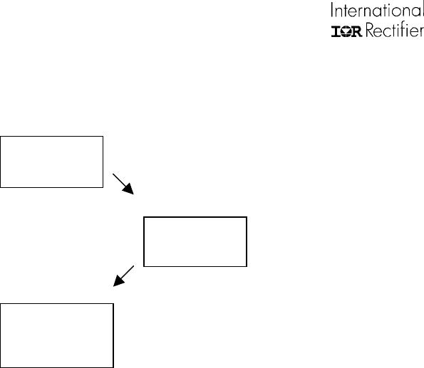
Ballast Output Stage
The components comprising the output stage are
selected using a set of equations. Different ballast
operating frequencies and their respective
voltages and currents are calculated.
The inductor and capacitor values are obtained
using equations (2) through (7). The results of
these equations reveal the location of each
operating frequency and the corresponding
voltages and currents. For a given L, C, DC bus
voltage, and pre-heat current, the resulting voltage
over the lamp during pre-heat is given as:
The resulting operating frequency during pre-heat
is given as:
ph
ph
ph
CV
I
f
π
2
=
[Hz] (3)
The resulting operating frequency during ignition
is given as:
LC
V
V
f
ign
DC
ign
π
π
4
1
2
1
+
=
[Hz] (4)
The total load current during ignition is given as:
IfCV
ign ign ign
= 2
π
[App] (5)
ππ
DC
ph
DC
ph
V
I
C
L
V
V
2
8
2
2
1
2
2
−
+
=
(2)