10
Figure 14. Recommended soldering pattern for HSMx-C110.
Figure 17. Reeling orientation.
Figure 18. Reel dimensions.
5.0 (0.200)
1.0 (0.039)
1.5
(0.059)
1.5
(0.059)
2.0
(0.079)
0.9 (0.035)
0.2 (0.008)
0.9 (0.035)
CENTERING
BOARD
0.7 (0.028)
0.8
(0.031)
0.8
(0.031)
1.2
(0.047)
0.4 (0.016)
0.15 (0.006)
0.4 (0.016)
CENTERING
BOARD
Figure 15. Recommended soldering pattern for HSMx-C120.
Note: All dimensions in millimeters (inches).
Figure 16. Recommended soldering pattern for HSMx-C265.
1.25 (0.049)
1.4
(0.055)
2.3
(0.091)
1.4
(0.055)
2.2 (0.087) DIA. PCB HOLE
10.50 ± 1.0 (0.413 ± 0.039)
59.60 ± 1.00
(2.346 ± 0.039)
Ø 20.20 MIN.
(Ø 0.795 MIN.)
6
PS
178.40 ± 1.00
(7.024 ± 0.039)
3.0 ± 0.5
(0.118 ± 0.020)
4.0 ± 0.5
(0.157 ± 0.020)
5.0 ± 0.5
(0.197 ± 0.020)
Ø 13.1 ± 0.5
(Ø 0.516 ± 0.020)
8.0 ± 1.0 (0.315 ± 0.039)
CATHODE SIDE
PRINTED LABEL
USER FEED DIRECTION
11
Figure 19. Tape dimensions.
8.00 ± 0.30
(0.315 ± 0.012)
USER FEED
DIRECTION
DIM. A
(SEE TABLE 1)
3.50 ± 0.05
(0.138 ± 0.002)
1.75 (0.069)
DIM. C
(SEE TABLE 1)
0.20 ± 0.05
(0.008 ± 0.002)
CARRIER TAPE
COVER TAPE
DIM. B
(SEE TABLE 1)
4.00 (0.157)
2.00 ± 0.05
(0.079 ± 0.002)
4.00 (0.157)
1.50 (0.059)
HSMx-C265 SERIES 3.70 (0.146) 1.45 (0.057) 1.30 (0.051)
TABLE 1
DIMENSIONS IN MILLIMETERS (INCHES)
CATHODE
DIM. A
± 0.10 (0.004)
DIM. B
± 0.10 (0.004)PART NUMBER
DIM. C
± 0.10 (0.004)
8.00 ± 0.30
(0.315 ± 0.012)
USER FEED
DIRECTION
DIM. A
(SEE TABLE 1)
3.50 ± 0.05
(0.138 ± 0.002)
1.75 (0.069)
DIM. C
(SEE TABLE 1)
0.20 ± 0.05
(0.008 ± 0.002)
CARRIER TAPE
COVER TAPE
DIM. B
(SEE TABLE 1)
4.00 (0.157)
2.00 ± 0.05
(0.079 ± 0.002)
4.00 (0.157)
1.50 (0.059)
TABLE 1
DIMENSIONS IN MILLIMETERS (INCHES)
CATHODE
DIM. A
± 0.10 (0.004)
DIM. B
± 0.10 (0.004)PART NUMBER
DIM. C
± 0.10 (0.004)
HSMx-C110/C120
POSITION IN
CARRIER TAPE
DIM. B
(SEE TABLE 1)
DIM. A
(SEE TABLE 1)
R 1.0 ± 0.05
(0.039 ± 0.002)
HSMx-C110 SERIES
HSMx-C120 SERIES
HSMx-C150 SERIES
HSMx-C170 SERIES
HSMx-C177 SERIES
HSMx-C190 SERIES
HSMx-C191 SERIES
HSMx-C197 SERIES
R 0.5 ± 0.05
(0.020 ± 0.002)
1.20 (0.047)
0.75 (0.030)
1.27 (0.050)
0.95 (0.037)
0.60 (0.024)
0.90 (0.035)
0.87 (0.034)
0.60 (0.024)
3.40 (0.134)
1.90 (0.075)
3.50 (0.138)
2.30 (0.091)
2.30 (0.091)
1.75 (0.069)
1.86 (0.073)
1.75 (0.069)
1.70 (0.067)
1.15 (0.045)
1.88 (0.074)
1.45 (0.057)
1.40 (0.055)
0.90 (0.035)
0.89 (0.035)
0.95 (0.037)
Notes:
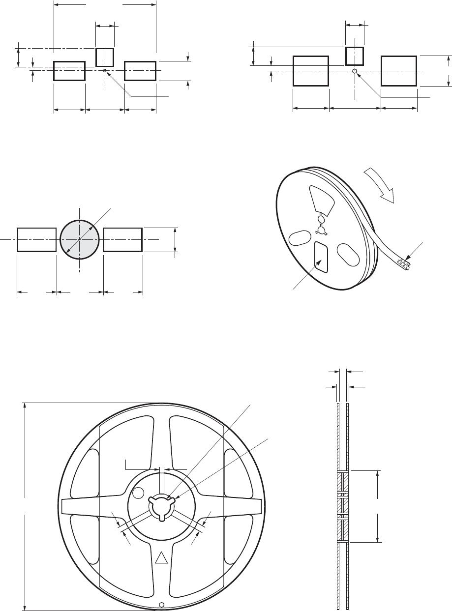
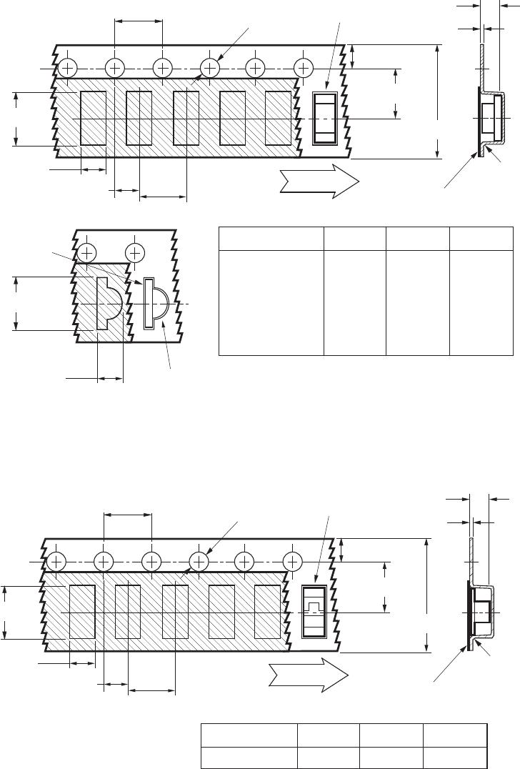
1. All dimensions in millimeters (inches).
2. Tolerance is ±0.1 mm (±0.004 in.)unless otherwise speci ed.
Figure 20. Tape leader and trailer dimensions.
Convective IR Re ow Soldering
For more information on IR re ow
soldering, refer to Application Note
1060, Surface Mounting SMT LED
Indicator Components.
Storage Condition: 5 to 30˚ C
@ 60% RH max.
Baking is required under the
condition:
a) Humidity Indicator Card is
>10% when read at 23 ± 5°C.
b) Device exposed to factory
conditions <30°C/60% RH
more than 672 hours.
Baking recommended condition: 60
+/– 5˚C for 20 hours.
END START
THERE SHALL BE A
MINIMUM OF 160 mm
(6.3 INCH) OF EMPTY
COMPONENT POCKETS
SEALED WITH COVER
TAPE.
MOUNTED WITH
COMPONENTS
THERE SHALL BE A
MINIMUM OF 160 mm
(6.3 INCH) OF EMPTY
COMPONENT POCKETS
SEALED WITH COVER
TAPE.
MINIMUM OF
230 mm
(9.05 INCH)
MAY CONSIST
OF CARRIER
AND/OR
COVER TAPE.
For product information and a complete list of distributors, please go to our website: www.avagotech.com
Avago, Avago Technologies, and the A logo are trademarks of Avago Technologies in the United States and other countries.
Data subject to change. Copyright © 2005-2012 Avago Technologies. All rights reserved. Obsoletes 5989-4806EN
AV02-0551EN - March 5, 2012

HSMG-C150

Mfr. #:
Manufacturer:
Broadcom / Avago
Description:
Standard LEDs - SMD Green Diffused 572nm 8mcd
Lifecycle:
New from this manufacturer.
Delivery:
DHL FedEx Ups TNT EMS
Payment:
T/T Paypal Visa MoneyGram Western Union