5
Absolute Maximum Ratings for GaP at T
A
=25°C
Parameter C110/150/265 C120/170/177/190/191/197 Units
DC Forward Current
[1]
25 20 mA
Power Dissipation 65 52 mW
Reverse Voltage (I
R
=100 μA) 5 5 V
LED Junction Temperature 95 95 °C
Operating Temperature Range -40 to +85 -40 to +85 °C
Storage Temperature Range -40 to +85 -40 to +85 °C
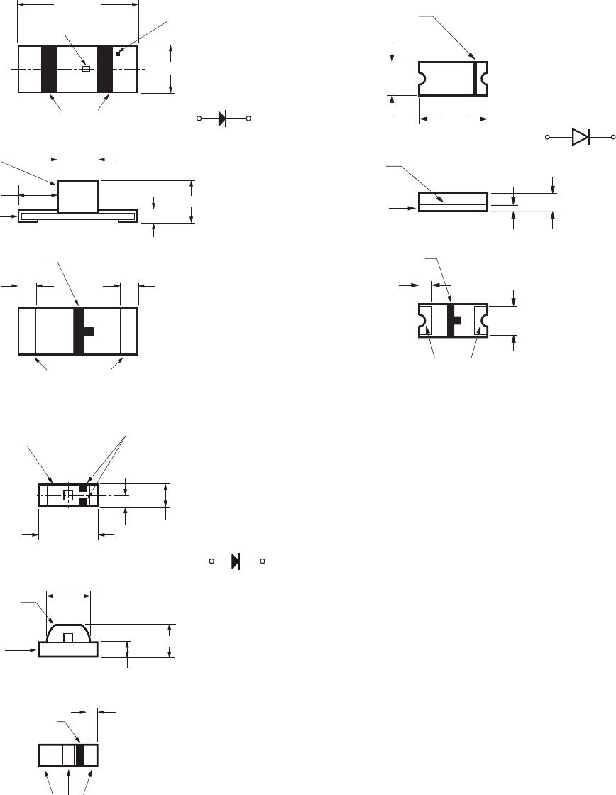
Soldering Temperature See re ow soldering pro le (Figure 9 & 10)
Absolute Maximum Ratings for AlGaAs at T
A
=25°C
Parameter C110/150 C120/170/190/191/265 Units
DC Forward Current
[1]
30 25 mA
Power Dissipation 78 65 mW
Reverse Voltage (I
R
=100μA) 5 5 V
LED Junction Temperature 95 95 °C
Operating Temperature Range -40 to +85 -40 to +85 °C
Storage Temperature Range -40 to +85 -40 to +85 °C
Soldering Temperature See re ow soldering pro le (Figure 9 & 10)
Electrical Characteristics at T
A
=25°C
Reverse Capacitance
Forward Voltage Breakdown C(pF), Thermal
Part Number Color V
F
(Volts) V
R
(Volts) @ V
F
= 0 V, Resistance
@ I
F
= 20 mA @ I
R
= 100 μA f = 1 MHz R
J-P
(°C/W)
Typ. Max. Min. Typ. Typ.
HSMS-C110/150 HER 2.1 2.6 5 5 400
HSMS-C120 350
HSMS-C170/177/190/191/197 250
HSMD-C110/150 Orange 2.2 2.6 5 7 400
HSMD-C120 350
HSMD-C170/177/190/191/197 250
HSMY-C110/150 Yellow 2.1 2.6 5 6 400
HSMY-C170/177/190/191/197 250
HSMG-C110/150 Green 2.2 2.6 5 9 400
HSMG-C120 350
HSMG-C170/177/190191/197/265 250
HSMH-C110/150 AlGaAs 1.8 2.6 5 18 460
HSMH-C120 400
HSMH-C170/190/191/265 300
Note:
1. Derate linearly as shown in Figure 4 for temperature above 25°C.