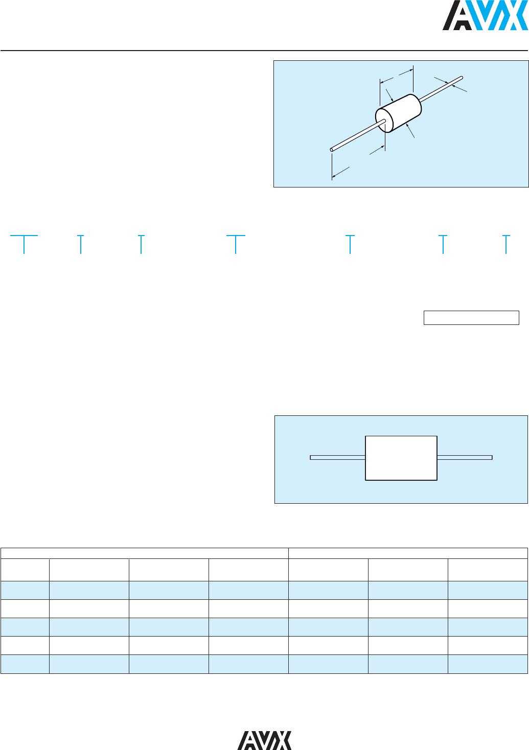
MARKING (EXAMPLE)
Line 1, A (for AVX), 5 = 50 Volts (V is optional),
E = TC Line 2, 104Z = Capacitance Code
Line 3, Tolerance, 2 digit Lot Code
Date Code: 8 = 2008
10 = Week
Four Digit Date Code Optional
Per MIL-Spec Case Size
AVX Lead
Style
MIL-C-11015 MIL-PRF-39014 MIL-PRF-20 Length (L) Diameter (D)
Diameter (LD)
MA10 CK12 CKR11 CCR75/CC75
4.07 ± .25 2.29 ± .25 .48 ± .05
(.160" ± .010") (.090" ± .010") (.019" ± .002")
MA20 CK13 CKR12 CCR76/CC76
6.35 ± .25 2.29 ± .25 .48 ± .05
(.250" ± .010") (.090" ± .010") (.019" ± .002")
MA40 CK14 CKR14 CCR77/CC77
9.91 ± .25 3.56 ± .25 .63 ± .05
(.390" ± .010") (.140" ± .010") (.025" ± .002")
MA50 CK15 CKR15 CCR78/CC78
12.7 ± .51 6.35 ± .38 .63 ± .05
(.500" ± .020") (.250" ± .015") (.025" ± .002")
MA60 CK16 CKR16 CCR79/CC79
17.53 ± .51 8.89 ± .51 .63 ± .05
(.690" ± .020") (.350" ± .015") (.025" ± .002")
For Military/Established Reliability Molded/Axial Lead see MIL-C-11015, MIL-PRF-39014, MIL-PRF-20 Section. Dimensions: Millimeters (Inches)
MILITARY CROSS REFERENCE AND DIMENSIONS GUIDE
AVX MA Series
Molded Axial Leaded MLC
Temperature Coefficient: C0G (NP0), X7R, Z5U
50V, 100V and 200V
Case Material: Molded Epoxy
Lead Material: Solderable
GENERAL DESCRIPTION
HOW TO ORDER
MA10
Molded
Axial Size
MA10
MA20
MA30
MA40
MA50
MA60
5
Voltage
5 = 50V
1 = 100V
2 = 200V
E
Dielectric
A = C0G (NP0)
C = X7R
E = Z5U
104
Capacitance
First two digits are the significant
figures of capacitance. Third digit
indicates the additional number
of zeros. For example, order
100,000 pF as 104. (For values
below 10pF use “R” in place of
decimal point, e.g., 1R4 = 1.4pF.)
Z
Capacitance
Tolerance
C0G (NP0):
F = ±1%
J = ±5%
K = ±10%
M = ±20%
D = ±0.5pF
<10pF only
X7R:
J = ±5%
K = ±10%
M = ±20%
Z5U:
M = ±20%
Z = +80%
-20%
A
Failure Rate
A = Not Applicable
A
Leads
A = Standard
‡ C tolerance available C0G (NP0) from 1.0 to 9.1 pF only. Minimum
tolerance for values 10 pF - 100 pF is D or F whichever is greater.
Not RoHS Compliant