LT1789-1/LT1789-10
9
1789fc
Note 1: Stresses beyond those listed under Absolute Maximum Ratings
may cause permanent damage to the device. Exposure to any Absolute
Maximum Rating condition for extended periods may affect device
reliability and lifetime.
Note 2: Does not include the effect of the external gain resistor R
G
.
Note 3: This parameter is not 100% tested.
Note 4: The LT1789C-1/ LT1789C-10 is guaranteed to meet specified
performance from 0°C to 70°C and is designed, characterized and
expected to meet these extended temperature limits, but is not tested at
–40°C and 85°C. The LT1789I-1/ LT1789I-10 is guaranteed to meet the
extended temperature limits.
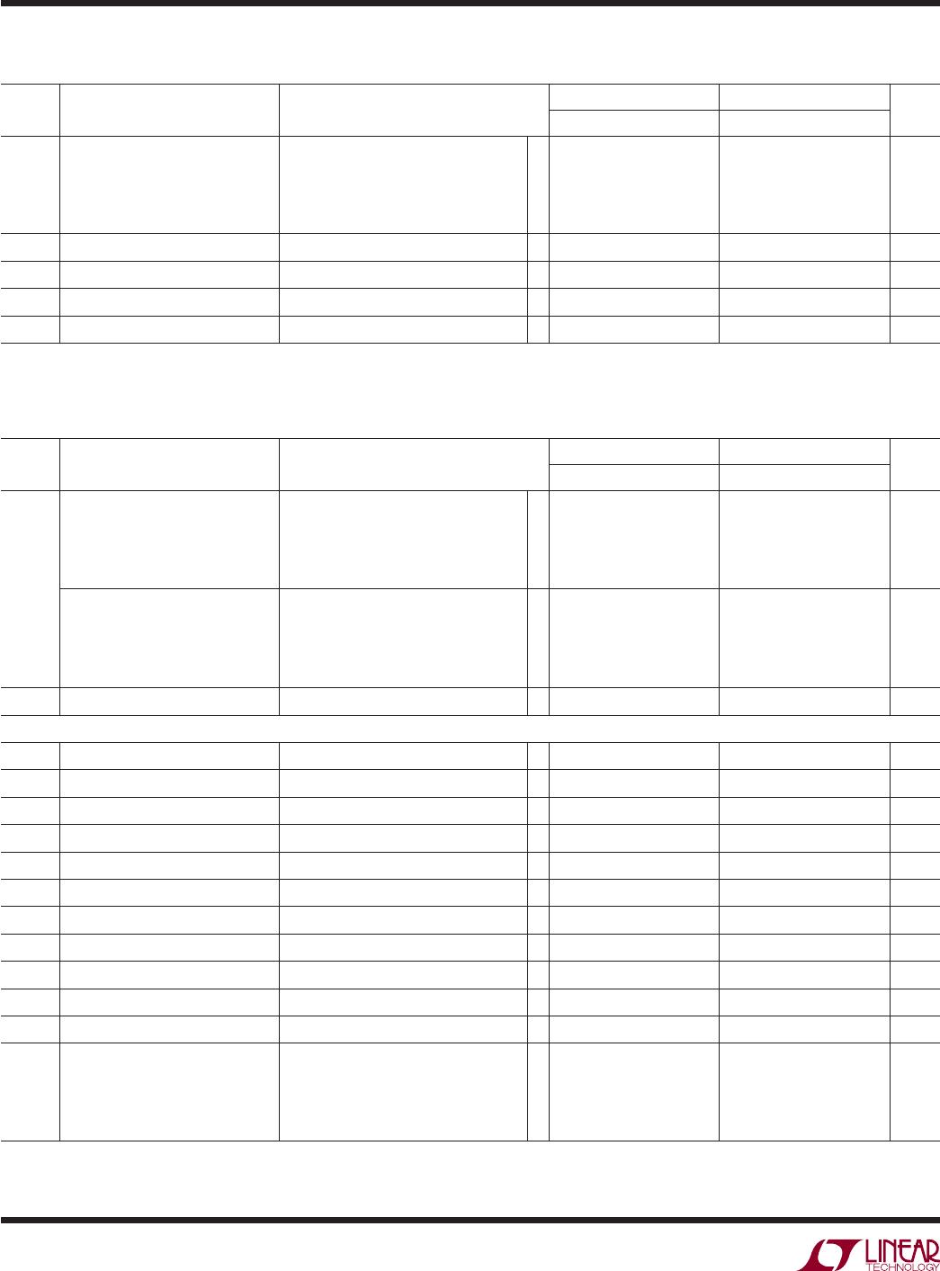
SYMBOL PARAMETER CONDITIONS
LT1789-1 LT1789-10
UNITSMIN TYP MAX MIN TYP MAX
PSRR Power Supply Rejection Ratio
LT1789-1, V
S
= ±1.25V to ±16V
LT1789-10, V
S
= ±1.50V to ±16V
G = 1
G = 10
G = 100, 1000
l
l
l
90
100
102
96
102
dB
dB
dB
Minimum Supply Voltage
l
±1.25 ±1.50 V
I
S
Supply Current
l
160 160 µA
V
O
Output Voltage Swing
l
±14.15 ±14.15 V
SR Slew Rate V
OUT
= ±10V
l
0.008 0.024 V/µs
ELECTRICAL CHARACTERISTICS
The l denotes the specifications which apply over the temperature range of
–40°C ≤ T
A
≤ 85°C. V
S
= ±15V, R
L
= 20k, V
CM
= V
REF
= 0V, unless otherwise noted. (Note 4)
Note 5: Hysteresis in offset voltage is created by package stress that
differs depending on whether the IC was previously at a higher or lower
temperature. Offset voltage hysteresis is always measured at 25°C, but
the IC is cycled to 85°C I-grade (or 70°C C-grade) or –40°C I-grade
(0°C C-grade) before successive measurement. 60% of the parts will
pass the typical limit on the data sheet.
Note 6: V
S
= 5V limits are guaranteed by correlation to V
S
= 3V and
V
S
= ±15V tests.
Note 7: V
S
= 3V limits are guaranteed by correlation to V
S
= 5V and
V
S
= ±15V tests.
Note 8: This parameter is not tested at V
S
= 3V on the LT1789-10 due
to an increase in sensitivity to test system noise. Actual performance is
expected to be similar to performance at V
S
= 5V.
TYPICAL PERFORMANCE CHARACTERISTICS
Supply Current vs Supply Voltage
Input Bias Current
vs Temperature
Input Bias Current
vs Common Mode Input Voltage
TOTAL SUPPLY VOLTAGE (V)
0
20
SUPPLY CURRENT (μA)
30
50
60
70
120
90
10
20
25
1789 G01
40
100
110
80
515
30
35
40
125°C
25°C
–55°C
TEMPERATURE (°C)
–50 –25
–25
INPUT BIAS CURRENT (nA)
–15
0
0
50
75
1789 G02
–20
–5
–10
25
100
125
V
S
= 5V, 0V
V
CM
= 2.5V
COMMON MODE INPUT VOLTAGE (V)
0
INPUT BIAS CURRENT (nA)
–18
–14
–10
4.5
1789 G03
–22
–26
–20
–16
–12
–24
–28
–30
1.5
2.5
3.5
10.5–0.5
5
2
3
4
V
S
= 5V, 0V
V
REF
= 2.5V
–55°C
125°C
25°C
85°C
(LT1789-1, LT1789-10)