LTC3025-1/LTC3025-2/
LTC3025-3/LTC3025-4
4
30251234ff
Note 1: Stresses beyond those listed under Absolute Maximum Ratings
may cause permanent damage to the device. Exposure to any Absolute
Maximum Rating condition for extended periods may affect device
reliability and lifetime.
Note 2: This IC includes overtemperature protection that is intended
to protect the device during momentary overload conditions. Junction
temperature will exceed 125°C when overtemperature protection is active.
Continuous operation above the specified maximum operating junction
temperature may impair device reliability.
Note 3: The LTC3025-X regulators are tested and specified under pulse
load conditions such that T
J
≈ T
A
. The LTC3025E-X are guaranteed to
meet performance specifications from 0°C and 125°C. Specifications over
the –40°C to 125°C operating junction temperature range are assured by
design, characterization and correlation with statistical process controls.
The LTC3025I-X are guaranteed to meet performance specifications over
the full –40°C to 125°C operating junction temperature range.
Note 4: For the LTC3025-1, a regulated output voltage will only be available
when the minimum IN and BIAS operating voltages as well as the IN to
OUT and BIAS to OUT dropout voltages are all satisfied. For the
LTC3025-2/LTC3025-3/LTC3025-4 the minimum IN operating voltage
assumes I
OUT
= 500mA. For correct regulation at I
OUT
< 500mA the
minimum IN operating voltage decreases to the maximum V
SENSE
Regulation Voltage as I
OUT
decreases to 0mA (i.e. V
INMIN
= 1.312V at I
OUT
= 250mA for the LTC3025-2).
Note 5: Operating conditions are limited by maximum junction
temperature. The regulated output voltage specification will not apply
for all possible combinations of input voltage and output current. When
operating at maximum input voltage, the output current range must be
limited. When operating at maximum output current, the input voltage
range must be limited.
Note 6: Dropout voltage is minimum input to output voltage differential
needed to maintain regulation at a specified output current. In dropout, the
output voltage will be equal to V
IN
– V
DROPOUT
.
The l denotes the specifications which apply over the full operating
temperature range, otherwise specifications are at T
A
= 25°C. V
IN
= 1.5V, V
BIAS
= 3.6V, C
OUT
= 1µF, C
IN
= 0.1µF, C
BIAS
= 0.1µF
(all capacitors ceramic) unless otherwise noted. (Note 3)
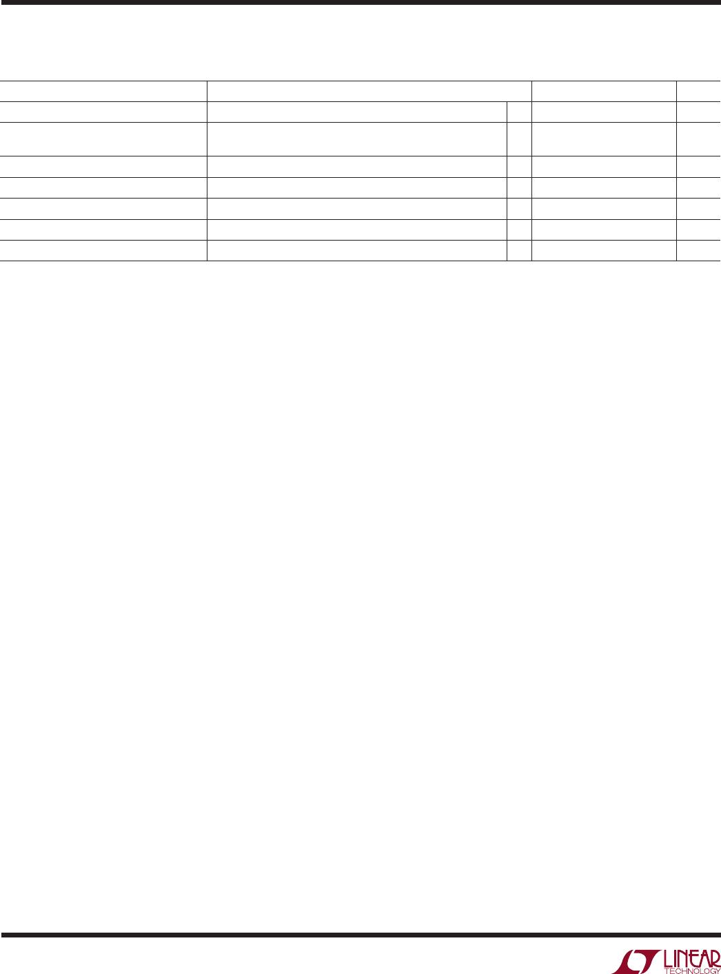
elecTrical characTerisTics
PARAMETER CONDITIONS MIN TYP MAX UNITS
I
OUT
Continuous Output Current
l
500 mA
I
OUT
Current Limit V
ADJ
= 0V(LTC3025-1),
V
SENSE
= 0V(LTC3025-2/LTC3025-3/LTC3025-4)
1130 mA
e
n
Output Voltage Noise f = 10Hz to 100kHz, I
OUT
= 300mA 80 µV
RMS
V
IH
SHDN Input High Voltage
l
0.9 V
V
IL
SHDN Input Low Voltage
l
0.3 V
I
IH
SHDN Input High Current SHDN = 1.2V –1 1 µA
I
L
SHDN Input Low Current SHDN = 0V –1 1 µA