SPECIFICATION
MODEL
DC VOLTAGE
RATED CURRENT
CURRENT RANGE
RATED POWER
OUTPUT
VOLTAGE ADJ. RANGE
LINE REGULATION
LOAD REGULATION
SETUP, RISE TIME
Note.4
HOLD UP TIME (Typ.)
VOLTAGE RANGE
FREQUENCY RANGE
EFFICIENCY (Typ.)
INPUT
ALARM
INRUSH CURRENT (Typ.)
LEAKAGE CURRENT
SAFETY STANDARDS
WORKING TEMP.
WORKING HUMIDITY
STORAGE TEMP., HUMIDITY
TEMP. COEFFICIENT
VIBRATION
MTBF
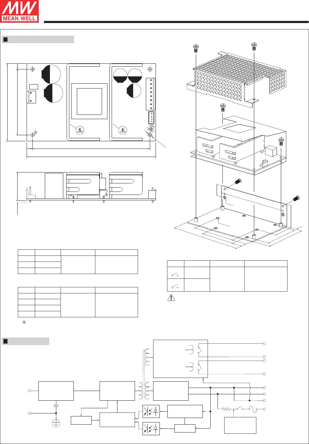
DIMENSIONOTHERS
NOTE
PACKING
OVERLOAD
OVER VOLTAGE
BATTERY CUT OFF
AC OK
Note.6
BATTERY LOW
AC CURRENT (Typ.)
2400ms, 30ms/230VAC 2400ms, 30ms/115VAC at full load
40ms/230VAC 14ms/115VAC at full load
90 ~ 264VAC 127 ~ 370VDC
47 ~ 63Hz
86%
CH1:28.98 ~ 37.26V
88%
20 1V±
2A/115VAC 1.2A/230VAC
COLD START 35A/115VAC 70A/230VAC
<1mA / 240VAC
105 ~ 150% rated output power
CH1:14.49 ~ 18.63V
Protection type : Hiccup mode, recovers automatically after fault condition is removed
Protection type : Shut down o/p voltage, re-power on to recover
10 0.5V±
UL60950-1, TUV EN60950-1, approvedEAC TP TC 004
Compliance to EN55032 (CISPR32) Class B, EN61000-3-2,-3, EAC TP TC 020
Compliance to EN61000-4-2,3,4,5,6,8,11, EN55024, light industry level, criteria A, EAC TP TC 020
-20 ~ +70 (Refer to "Derating Curve")℃
20 ~ 90% RH non-condensing
-20 ~ +85 , 10 ~ 95% RH℃
10 ~ 500Hz, 2G 10min./1cycle, 60min. each along X, Y, Z axes
417.6K hrs min. MIL-HDBK-217F (25 )℃
PCB:127*76.2*31mm (L*W*H) ; Enclosed type:130*85*37mm (L*W*H)
PCB:0.23Kg; 63pcs/15.5Kg/1.35CUFT ; Enclosed type:0.44Kg;32pcs/15Kg/0.64CUFT
File Name:PSC-100-SPEC 2018-01-12
FUNCTION
Battery low voltage : < 11V Battery low voltage : < 22V
Relay contact output, ON : AC OK ; OFF : AC Fail ; Max. rating : 30V / 1A
Relay contact output, OFF : Battery OK ; ON : Battery Low ; Max. rating : 30V / 1A
PSC-100B
27.6V
CH1
2.4A
0 ~ 3.5A
100.74W
100mVp-p
CH1: 24 ~ 29V
±1.0%
±0.5%
±0.5%
27.6V
CH2
1.25A
--------
--------
--------
--------
--------
13.8V
CH2
2.5A
--------
--------
--------
--------
--------
PSC-100A
13.8V
4.75A
0 ~ 7A
100.05W
100mVp-p
CH1: 12 ~ 15V
±1.0%
±0.5%
±0.5%
100W Single Output with Battery Charger(UPS Function)
Universal AC input / Full range
5"x3" compact size
Models with L-Bracket and cover available (PSC-100x-C, x=A,B)
Protections: Short circuit / Overload / Over voltage
Battery low protection / Battery reverse polarity protection by fuse
Relay contact signal output for AC OK and Battery Low
Cooling by free air convection
100% full load burn-in test
2 years warranty
PSC-100 series
RIPPLE & NOISE (max.) Note.2
VOLTAGE TOLERANCE Note.3
ENVIRONMENT
PROTECTION
WITHSTAND VOLTAGE
ISOLATION RESISTANCE
I/P-O/P:3KVAC I/P-FG:2KVAC O/P-FG:0.5KVAC
I/P-O/P, I/P-FG, O/P-FG:100M Ohms / 500VDC / 25 / 70% RH℃
SAFETY &
EMC
(Note 4)
1. All parameters NOT specially mentioned are measured at 230VAC input, rated load and 25 of ambient temperature.¢
2. Ripple & noise are measured at 20MHz of bandwidth by using a 12" twisted pair-wire terminated with a 0.1uf & 47uf parallel capacitor.
3. Tolerance : includes set up tolerance, line regulation and load regulation.
4. Length of set up time is measured at first cold start. Turning ON/OFF the power supply may lead to increase of the set up time.
5. Heat sink HS2,HS3 can not be shorted.
6. Heat sink HS2,HS3 must have safety isolation distance from system case.
7. The power supply is considered a component which will be installed into a final equipment. All the EMC tests are been executed by mounting the unit on
a mm* mm metal plate with 1mm of thickness. The final equipment must be re-confirmed that it still meets EMC directives.230 230 For guidance on how to
perform these EMC tests, please refer to EMI testing of component power supplies. (as available on http://www.meanwell.com)
8. Please refer to suggest application (2) (4) in page 3.、
9. The ambient temperature derating of 3.5 /1000m with fanless models and of 5 /1000m with fan models for operating altitude higher than 2000m(6500ft).℃℃
CH1
OUTPUT NUMBER
EMC IMMUNITY
EMC EMISSION
PSC-100A -C =Blank,-C ; Blank=PCB only, -C=Enclosed type=Blank,-C ; Blank=PCB only, -C=Enclosed type
±℃℃0.03%/ (0~50 ) on CH1 output
Bauar
Sicherheit
egel gema
t gepruft
od
be
www.
ID 2000000000
tuv.com
wac g
os