MRS16, MRS25
www.vishay.com
Vishay BCcomponents
Revision: 07-Mar-16
2
Document Number: 28724
For technical questions, contact: filmresistorsleaded@vishay.com
THIS DOCUMENT IS SUBJECT TO CHANGE WITHOUT NOTICE. THE PRODUCTS DESCRIBED HEREIN AND THIS DOCUMENT
ARE SUBJECT TO SPECIFIC DISCLAIMERS, SET FORTH AT www.vishay.com/doc?91000
APPLICATION INFORMATION
The power dissipation on the resistor generates a temperature rise against the local ambient, depending on the heat flow
support of the printed-circuit board (thermal resistance). The rated dissipation applies only if the permitted film temperature is
not exceeded. Furthermore, a high level of ambient temperature or of power dissipation may raise the temperature of the solder
joint, hence special solder alloys or board materials may be required to maintain the reliability of the assembly.
These resistors do not feature a limited lifetime when operated within the permissible limits. However, resistance value drift
increasing over operating time may result in exceeding a limit acceptable to the specific application, thereby establishing a
functional lifetime. The designer may estimate the performance of the particular resistor application or set certain load and
temperature limits in order to maintain a desired stability.
Notes
• The PART NUMBER is shown to facilitate the introduction of a unified part numbering system for ordering products
(1)
Please refer packaging table
MAXIMUM RESISTANCE CHANGE AT RATED DISSIPATION
Operation mode Power
Climatic category -55 °C / +155 °C / 56 days
Rated dissipation, P
70
MRS16 0.4 W
MRS25 0.6 W
Applied maximum film temperature,
F max.
155 °C
Max. resistance change at rated
dissipation |R/R max.|, after:
MRS16 4.99 to 1 M
1000 h ± (0.5 % R + 0.05 )
MRS25 1to 10 M
1000 h ± (0.5 % R + 0.05 )
PART NUMBER AND PRODUCT DESCRIPTION
PART NUMBER: MRS16000C5119FCT00
TYPE VARIANT TCR RESISTANCE TOLERANCE PACKAGING
(1)
SPECIAL
MRS1600
MRS2500
0 = neutral C = ± 50 ppm/K 3 digit value
1 digit multiplier
MULTIPLIER
F = ± 1 % RP
CT
C1
Up to 2 digits
00 = standard
7 = *10
-3
8 = *10
-2
9 = *10
-1
0 = *10
0
1 = *10
1
2 = *10
2
3 = *10
3
4 = *10
4
5 = *10
5
6 = *10
6
PRODUCT DESCRIPTION: MRS16 50 1 % CT 51R1
MRS16 50 1 % CT 51R1
TYPE TCR TOLERANCE PACKAGING
(1)
RESISTANCE VALUE
MRS16
MRS25
± 50 ppm/K ± 1 % RP
CT
C1
51R1 = 51.1
1K = 1 k
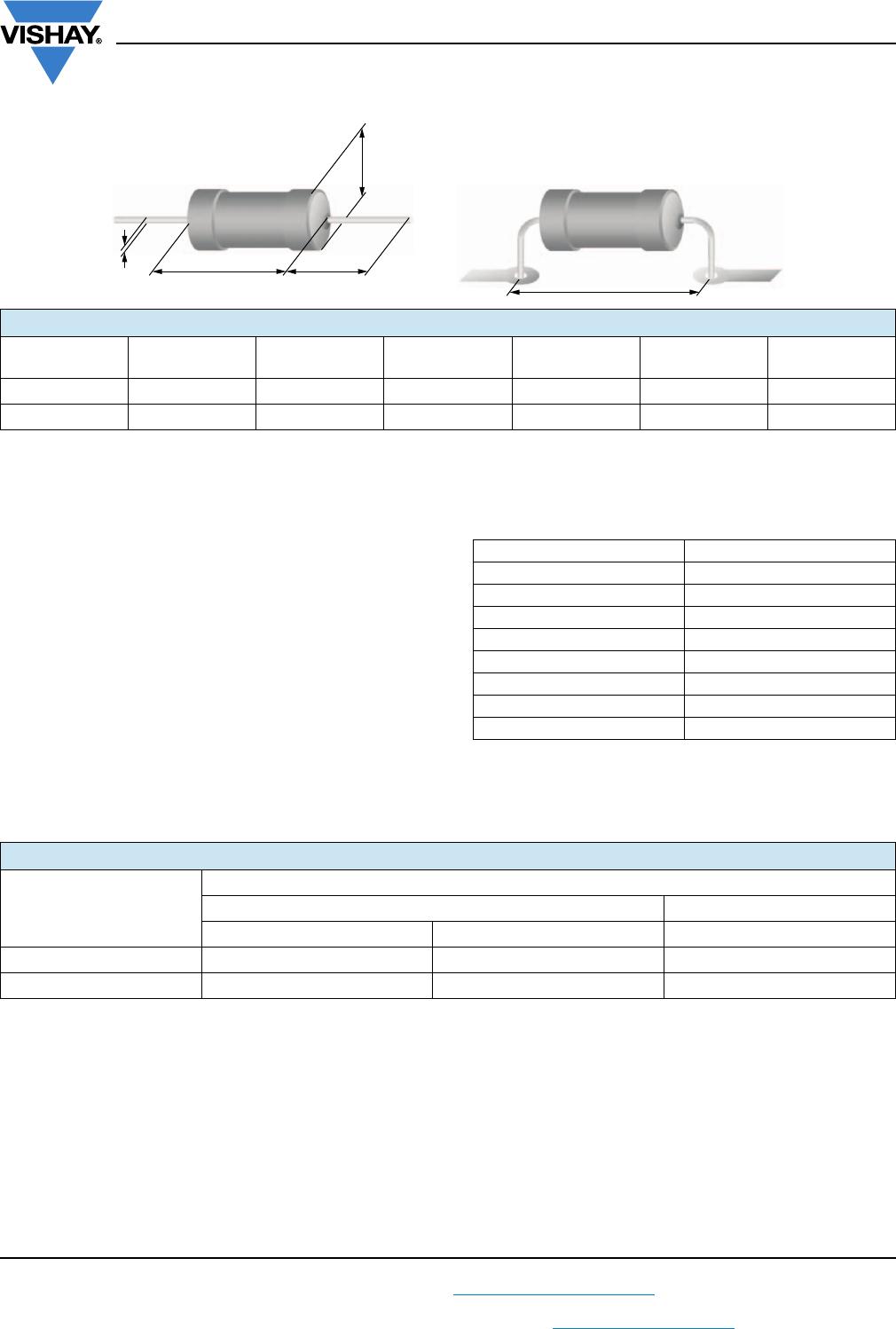
PACKAGING
TYPE CODE QUANTITY PACKAGING STYLE WIDTH PITCH DIMENSIONS
MRS16
MRS25
C1 1000
Taped acc. to IEC 60286-1
fan-folded in a box
53
mm
5
mm
184 mm x 75 mm x 42 mm
CT 5000 330 mm x 75 mm x 55 mm
RP 5000
Taped acc. to IEC 60286-1
on a reel
242 mm x 76 mm x 86 mm
M R S 1 6 0 0 0 C 5 1 1 9 F 0C T 0