ERL (Military RLR)
www.vishay.com
Vishay Dale
Revision: 19-Nov-12
1
Document Number: 31023
For technical questions, contact: ff2aresistors@vishay.com
THIS DOCUMENT IS SUBJECT TO CHANGE WITHOUT NOTICE. THE PRODUCTS DESCRIBED HEREIN AND THIS DOCUMENT
ARE SUBJECT TO SPECIFIC DISCLAIMERS, SET FORTH AT www.vishay.com/doc?91000
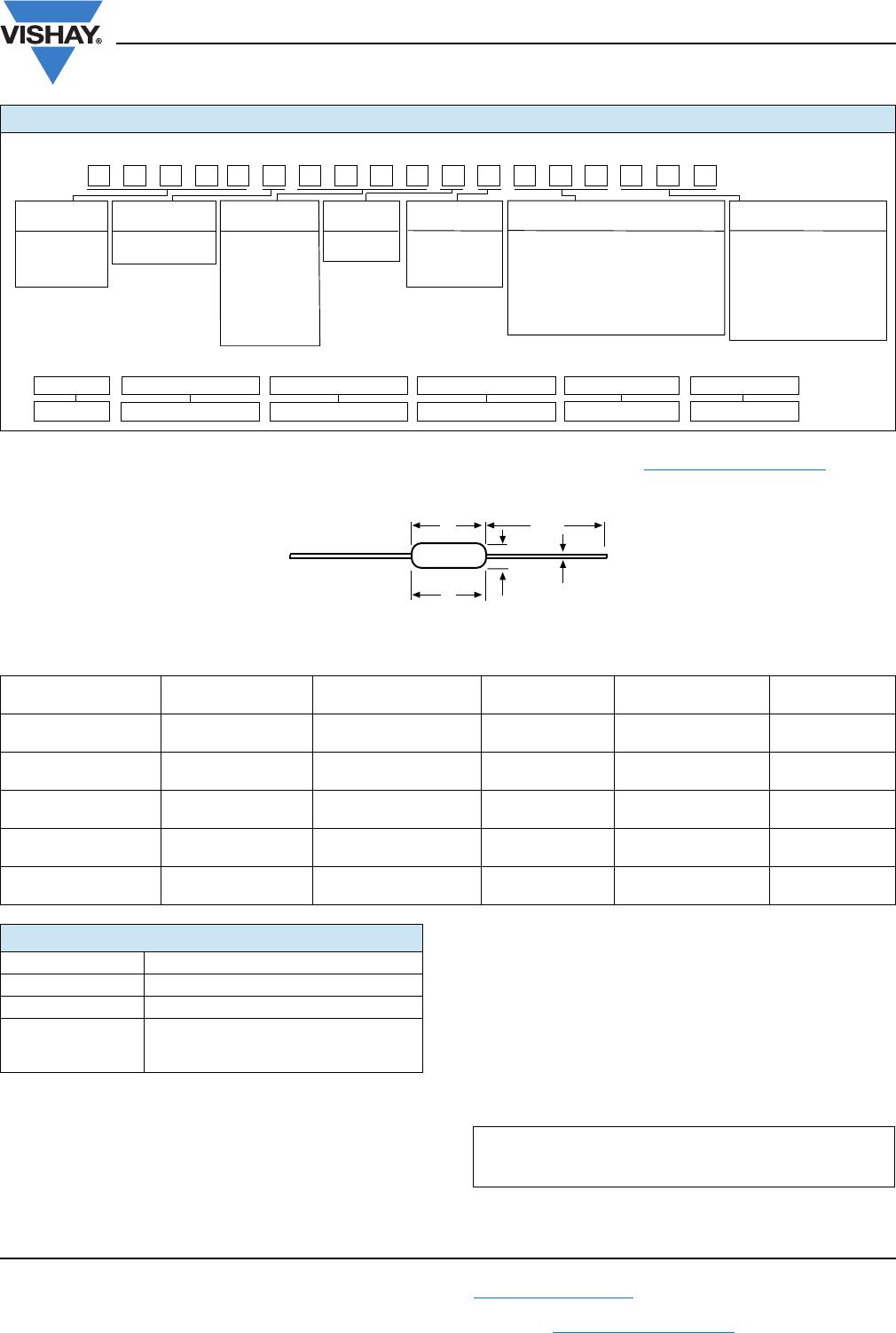
Metal Film Resistors, Military/Established Reliability,
MIL-PRF-39017 Qualified, Type RLR
FEATURES
• Meets requirements of MIL-PRF-39017
• Failure rate: Verified failure rate (contact factory for current
level)
• Epoxy coated construction provides superior moisture
protection
• Traceability of materials and processing
• Monthly lot acceptance testing
• Very low noise (- 40 dB)
• Extensive stocking program at distributors and factory in
± 1 % and ± 2 % tolerances
• Vishay Dale has complete capability to develop specific
reliability programs designed to customer requirements
Notes
(1)
Extended Resistance Range: DSCC has created a series of drawings intended to support extended resistance ranges left otherwise void by
the discontinuation of MIL-R-39008 RCR carbon composition resistors. Vishay Dale is listed as a resource on these drawings as follows:
• Low inductance: DSCC has created a drawing intended to support a resistor which exhibits low inductance over a frequency range of 1 MHz
to 30 MHz. Vishay Dale is listed as a resource on these drawings as follows:
These drawings can be viewed at: http://www.landandmaritime.dla.mil/Programs/MilSpec/ListDwgs.aspx?DocTYPE=DSCCdwg
(2)
Consult factory for current QPL failure rates
(3)
Hot solder dipped leads
(4)
Continuous working voltage shall be or maximum working voltage, whichever is less.
STANDARD ELECTRICAL SPECIFICATIONS
VISHAY
DALE
MODEL
MIL-PRF-39017
STYLE
MIL
SPEC.
SHEET
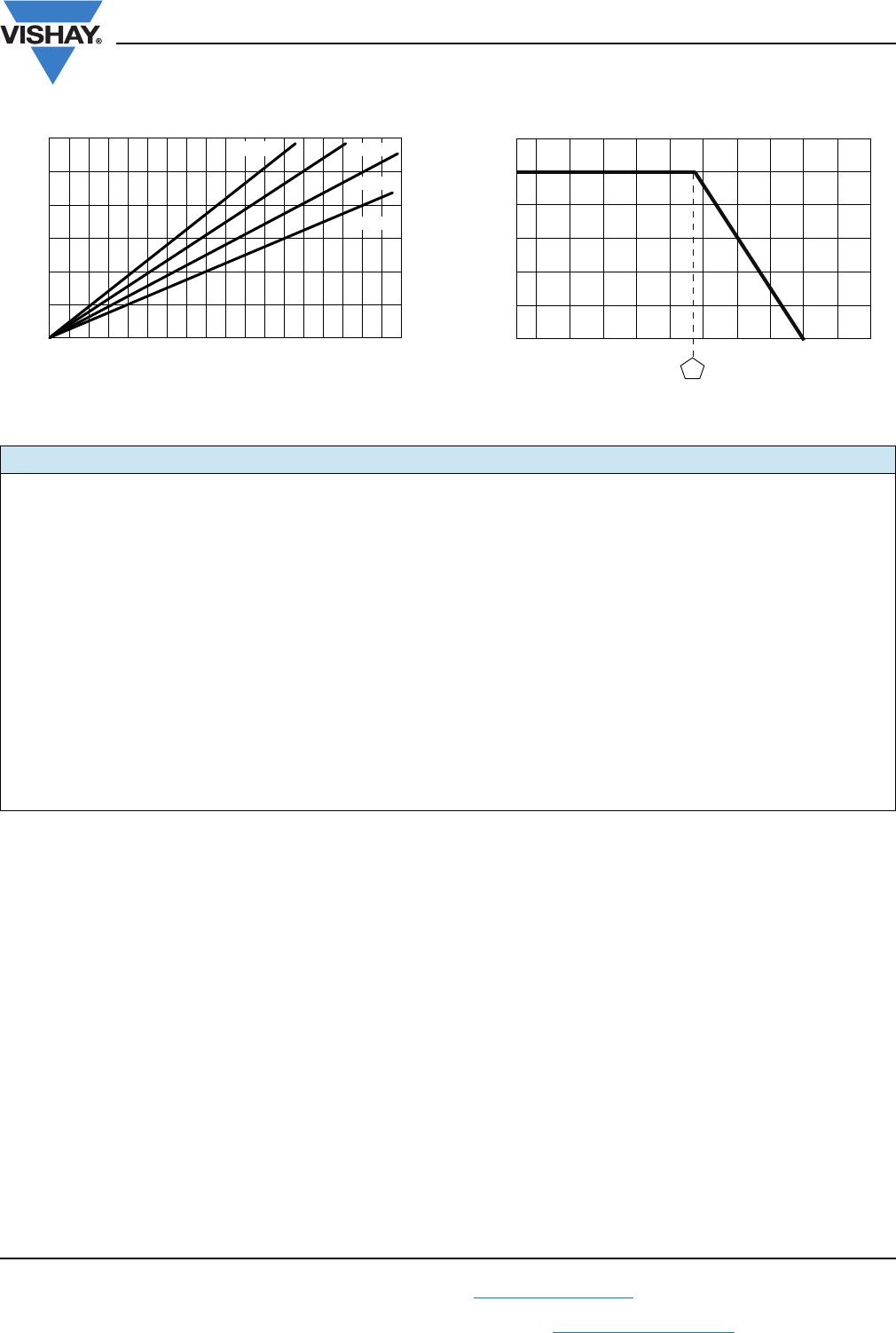
POWER
RATING
70 °C
W
RESISTANCE
RANGE
(1)
TOLERANCE
± %
TEMPERATURE
COEFFICIENT
±
ppm
/°C
MAXIMUM
WORKING
VOLTAGE
(4)
V
LIFE
FAILURE
RATE
(2)
ERL05,
ERL05..19
(3)
RLR05 05 0.125
4.7 to 301K
1, 2 100 200
M, P, R, S
302K to 1M M, P, R
ERL07,
ERL07..23
(3)
RLR07 01 0.25
1 to 9.76
1, 2 100 250
M
10 to 3.01M M, P, R, S
3.02M to 10M M, P, R
ERL20,
ERL20..11
(3)
RLR20 02 0.50 4.3 to 3.01M 1, 2 100 350 M, P, R
ERL32,
ERL32..1
(3)
RLR32 03 1.0 1 to 2.7M 1, 2 100 500 M, P, R
DSCC
DRAWING
NUMBER
VISHAY DALE
MODEL
POWER RATING
P
70 °C
W
RESISTANCE
RANGE
TOLERANCE
± %
TEMPERATURE
COEFFICIENT
± ppm/°C
MAXIMUM
WORKING
VOLTAGE
V
(4)
98020 ERL05..36, ERL05..37
(3)
0.125 1.1M to 22M 2, 5, 10 350 200
99011 ERL07..100, ERL07..101
(3)
0.25 11M to 22M 2, 5, 10 350 250
98021 ERL20..36, ERL20..37
(3)
0.50 3.3M to 22M 2, 5, 10 350 350
98022 ERL32..36, ERL32..37
(3)
1.0 3M to 22M 2, 5, 10 350 350
97004 ERL62..1, ERL62..2
(3)
2.0
10 to 2.7M
3M to 22M
1, 2, 5, 10
100
350
500
DSCC
DRAWING
NUMBER
VISHAY DALE
MODEL
POWER
RATING
P
70 °C
W
RESISTANCE
RANGE
MAXIMUM
INDUCTANCE
n
H
TOLERANCE
± %
TEMPERATURE
COEFFICIENT
± ppm/°C
MAXIMUM
WORKING
VOLTAGE
V
(4)
96002 ERL07..62 0.25
1 to 10 10
1, 2 100 250
11 to 49.9 8
TECHNICAL SPECIFICATIONS
PARAMETER UNIT CONDITION
Voltage Coefficient, max. ppm/V 5/V when measured between 10 % and full rated voltage
Dielectric Strength V
AC
RLR05 = 300; RLR07 and RLR20 = 500; RLR32 = 1000
Insulations Resistance 10
9
min. dry; 10
11
min. after moisture test
Operating Temperature Range °C - 65 to + 150
Terminal Strength lb 2 lb pull test on RLR05; 5 lb pull test on all other sizes
Solderability Continuous satisfactory coverage when tested in accordance with MIL-STD-202, Method 208
Weight g RLR05 = 0.11; RLR07 = 0.35; RLR20 = 0.75; RLR32 = 1.50