Expand menu
Hello, Sign in
My Account
0
Cart
Home
Products
Sensors
Semiconductors
Passive Components
Connectors
Power
Electromechanical
Optoelectronics
Circuit Protection
Integrated Circuits - ICs
Main Products
Manufacturers
Blog
Services
About OMO
About Us
Contact Us
Check Stock
CD214B-T43ALF
P1-P3
P4-P5
Specifications are subject to change without notice.
Customers should verify actual device performance in their specific applications.
CD214B Transient Voltage Suppressor Diode Series
Rating and Characteristic Curves
Pulse Derating Curve
Maximum Non-Repetitive Surge Current
100
75
50
25
0
05
0
25
75
100
150
125
175
200
Ambient Temperature (
Peak Pulse Derating in Percent of
Peak Power or Current
°C
)
10 x 1000 Waveform as Defined
by R.E.A.
Peak Forward Surge Current (Amps)
120
80
100
60
40
20
0
1
2
5
10
20
50
100
Number of Cycles at 60 Hz
Pulse Width 8.3 ms
Single Half Sine-Wave
(JEDEC Method)
Pulse W
aveform
T
ypical Junction Capacitance
100
50
0
0
1.0
2.0
3.0
4.0
T, Time (ms)
I
P
, Peak Pulse Current (%)
TA=25 °C
TP
TR=10 µs
Half value=
IRSM
2
Peak value (IRSM)
Pulse width (TP)
is defined as that point
where the peak current
decays to 50 % of IPSM.
10 x 1000 waveform
as defined by R.E.A.
Capacitance (pF)
10000
100
0
0
10
100
1000
Standoff Voltage (Volts)
1000
Bidirectional
TA = 25 °C
Unidirectional
Pulse Rating Curve
Steady State Power Derating Curve
100
10
1.0
0.1
0.1 µs
1.0 µs
10 µs
10 ms
TP, Pulse Width
P
P
, Peak Power (KW)
100 µs
1.0 ms
TA = 25 °C
Non-repetitive
Pulse Waveform
Shown in Pulse Waveform Graph
5.0 mm Lead Areas
5.0
3.0
4.0
2.0
1.0
0.0
05
0
25
75
100
150
125
175
200
TL, Lead Temperature (°C)
RM(AV) Steady State Power Dissipation (W)
60 Hz Resistive or
Inductive Load
Specifications are subject to change without notice.
Customers should verify actual device performance in their specific applications.
CD214B Transient Voltage Suppressor Diode Series
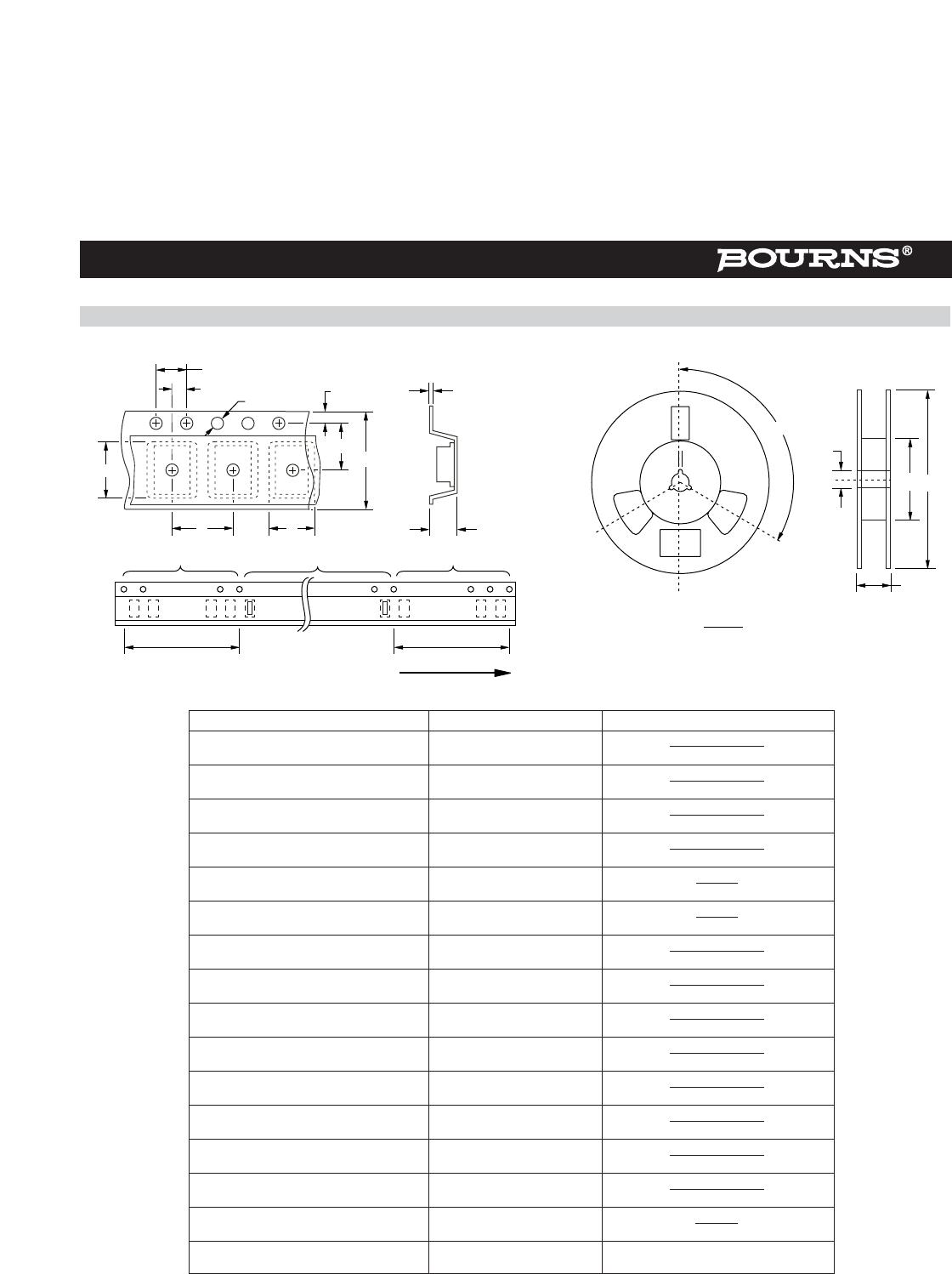
Packaging Information
The product will be dispensed in T
ape and Reel format (see diagram below).
.......
.......
.......
.......
.......
.......
.......
.......
P
A
F
E
T
120
°
D
2
D
D
1
W
1
C
Index Hole
P
0
P
1
W
B
10 pitches (min.)
Direction of Feed
10 pitches (min.)
End
Trailer
Device
Leader
Start
d
Devices are packed in accor
dance with EIA standard
RS-481-A and specifications shown here.
MM
(INCHES)
DIMENSIONS:
Item
Symbol
SMB (DO-214AA)
Carrier Width
A
4.94 ± 0.10
(0.194 - 0.004)
Carrier Length
B
5.57 ± 0.10
(0.210 - 0.004)
Carrier Depth
C
2.36 ± 0.10
(0.093 - 0.004)
Sprocket Hole
d
1.55 ± 0.05
(0.061 - 0.002)
Reel Outside Diameter
D
330
(12.992)
Reel Inner Diameter
D
1
50.0
MIN.
(1.969)
Feed Hole Diameter
D
2
13.0 ± 0.20
(0.512 - 0.008)
Sprocket Hole Position
E
1.75 ± 0.10
(0.069 - 0.004))
Punch Hole Position
F
5.50 ± 0.05
(0.217 - 0.002)
Punch Hole Pitch
P
4.00 ± 0.10
(0.157 - 0.004)
Sprocket Hole Pitch
P
0
4.00 ± 0.10
(0.157 - 0.004)
Embossment Center
P
1
2.00 ± 0.05
(0.079 - 0.002)
Overall T
ape Thickness
T
0.30 ± 0.10
(0.012 - 0.004)
T
ape Width
W
12.00 ± 0.20
(0.472 - 0.008)
Reel Width
W
1
18.4
MAX.
(0.724)
Quantity per Reel
--
3,000
REV. 03/10
P1-P3
P4-P5
CD214B-T43ALF
Mfr. #:
Buy CD214B-T43ALF
Manufacturer:
Bourns
Description:
ESD Suppressors / TVS Diodes TVS Unidirect Diode 43VOLT
Lifecycle:
New from this manufacturer.
Delivery:
DHL
FedEx
Ups
TNT
EMS
Payment:
T/T
Paypal
Visa
MoneyGram
Western
Union
Products related to this Datasheet
ESDA8P80-1U1M
CD214B-T7.0ALF
CD214B-T15CALF
CD214B-T6.0ALF
CD214B-T110ALF
CD214B-T26ALF
CD214B-T28ALF
CD214B-T43ALF
CD214B-T58ALF
CD214B-T13ALF
CD214B-T54ALF
CD214B-T30ALF
CD214B-T150ALF
CD214B-T18ALF
CD214B-T120ALF
CD214B-T20ALF
CD214B-T12ALF
CD214B-T130ALF
CD214B-T33ALF
CD214B-T16ALF
CD214B-T14ALF
CD214B-T85ALF
CD214B-T5.0ALF
CD214B-T40ALF
CD214B-T7.5ALF
CD214B-T90ALF
CD214B-T45ALF
CD214B-T22ALF
CD214B-T170ALF
CD214B-T64ALF
CD214B-T6.5ALF
CD214B-T100ALF
CD214B-T51ALF
CD214B-T8.0ALF
CD214B-T17ALF
CD214B-T11ALF