MMKP383
www.vishay.com
Vishay BCcomponents
Revision: 15-Jan-15
10
Document Number: 28173
For technical questions, contact: dc-film@vishay.com
THIS DOCUMENT IS SUBJECT TO CHANGE WITHOUT NOTICE. THE PRODUCTS DESCRIBED HEREIN AND THIS DOCUMENT
ARE SUBJECT TO SPECIFIC DISCLAIMERS, SET FORTH AT www.vishay.com/doc?91000
POWER DISSIPATION AND MAXIMUM COMPONENT TEMPERATURE RISE
The power dissipation must be limited in order not to exceed the maximum allowed component temperature rise as a function
of the free air ambient temperature.
The power dissipation can be calculated according type detail specification “HQN-384-01/101: Technical information film
capacitors with the typical tgd of the curves.”.
The component temperature rise (T) can be measured (see section “Measuring the component temperature” for more details)
or calculated by T = P/G:
T = component temperature rise (°C)
P = power dissipation of the component (mW)
G = heat conductivity of the component (mW/°C)
MEASURING THE COMPONENT TEMPERATURE
A thermocouple must be attached to the capacitor body as in:
The temperature is measured in unloaded (T
amb
) and maximum loaded condition (T
c
).
The temperature rise is given by T = T
c
- T
amb
.
To avoid radiation or convection, the capacitor should be tested in a wind-free box.
HEAT CONDUCTIVITY (G) AS A FUNCTION OF (ORIGINAL) PITCH AND CAPACITOR BODY
THICKNESS IN mW/°C
W
max.
(mm)
HEAT CONDUCTIVITY (mW/°C)
PITCH 7.5 mm PITCH 10 mm PITCH 15 mm PITCH 22.5 mm PITCH 27.5 mm PITCH 37.5 mm
3.0 4 - - - - -
4.0 5 6.5 - - - -
4.5 5 - - - -
5.0 6 7.5 10 - - -
6.0 - 9.0 11 19 - -
7.0 - - 12 21 - -
8.5 - - 16 25 - -
9.0 - - - - 31 -
10.0 - - 18 28 - -
11.0 - - - - 36 -
13.0 - - - - 42 -
15.0 - - - - 48 -
18.0 - - - - 57 -
18.5 - - - - - 89
21.0 - - - - 68 -
21.5 - - - - - 102
24.0 - - - - - 116
30.0 - - - - - 134
Thermocouple
MMKP383
www.vishay.com
Vishay BCcomponents
Revision: 15-Jan-15
11
Document Number: 28173
For technical questions, contact: dc-film@vishay.com
THIS DOCUMENT IS SUBJECT TO CHANGE WITHOUT NOTICE. THE PRODUCTS DESCRIBED HEREIN AND THIS DOCUMENT
ARE SUBJECT TO SPECIFIC DISCLAIMERS, SET FORTH AT www.vishay.com/doc?91000
APPLICATION NOTE AND LIMITING CONDITIONS
For capacitors connected in parallel, normally the proof voltage and possibly the rated voltage must be reduced. For information
depending of the capacitance value and the number of parallel connections contact: dc-film@vishay.com
These capacitors are not suitable for mains applications as across-the-line capacitors without additional protection, as
described hereunder. These mains applications are strictly regulated in safety standards and therefore electromagnetic
interference suppression capacitors conforming the standards must be used.
To select the capacitor for a certain application, the following conditions must be checked:
1. The peak voltage (U
p
) shall not be greater than the rated DC voltage (U
RDC
)
2. The peak-to-peak voltage (U
p-p
) shall not be greater than the maximum (U
p-p
) to avoid the ionization inception level
3. The voltage pulse slope (dU/dt) shall not exceed the rated voltage pulse slope in an RC-circuit at rated voltage and without
ringing. If the pulse voltage is lower than the rated DC voltage, the rated voltage pulse slope may be multiplied by U
RDC
and
divided by the applied voltage.
For all other pulses following equation must be fulfilled:
T is the pulse duration
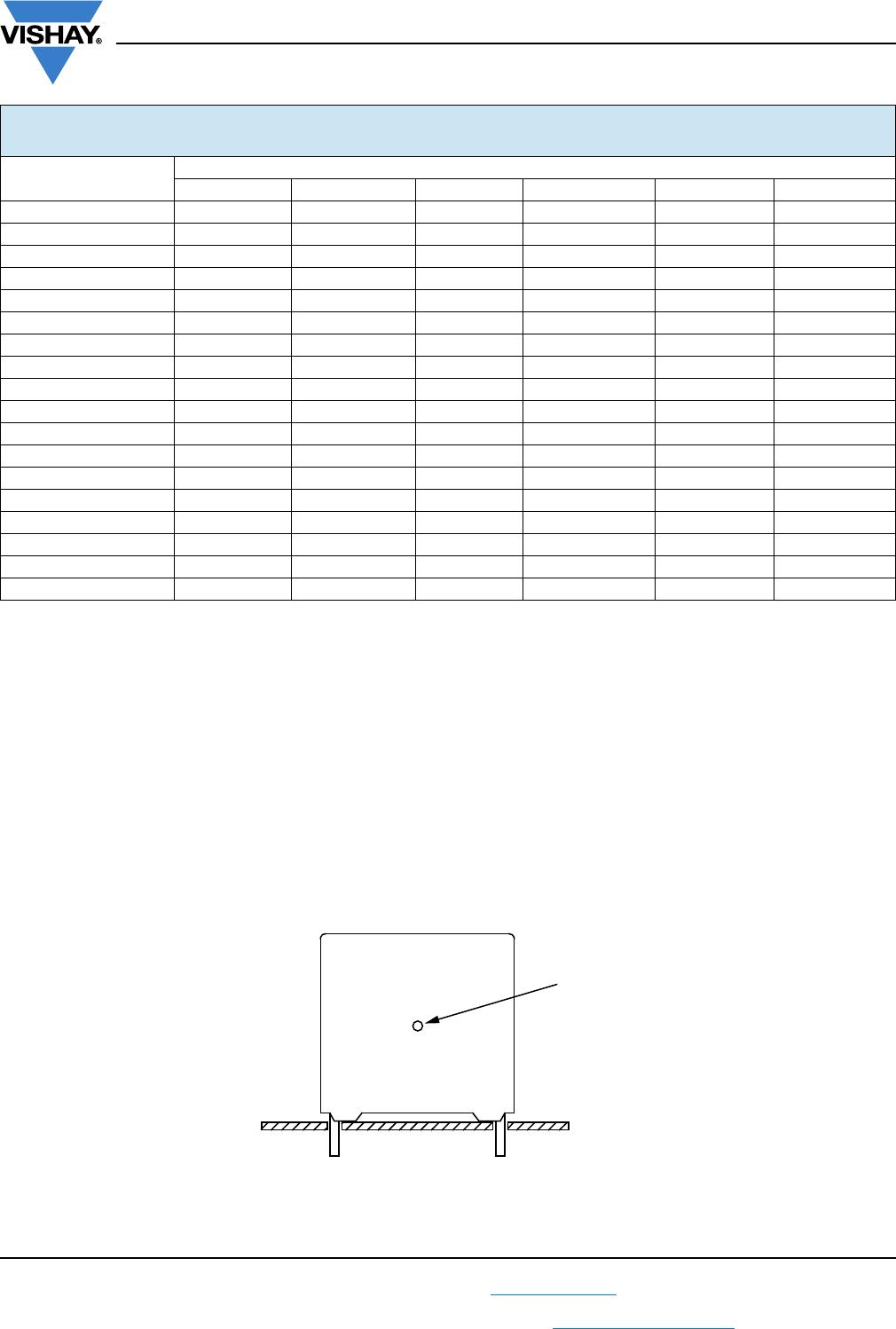
4. The maximum component surface temperature rise must be lower than the limits (see graph max. allowed component
temperature rise).
5. Since in circuits used at voltages over 280 V peak-to-peak the risk for an intrinsically active flammability after a capacitor
breakdown (short circuit) increases, it is recommended that the power to the component is limited to 100 times the values
mentioned in the table: “Heat Conductivity”
6. When using these capacitors as across-the-line capacitor in the input filter for mains applications or as series connected
with an impedance to the mains the applicant must guarantee that the following conditions are fulfilled in any case (spikes
and surge voltages from the mains included).
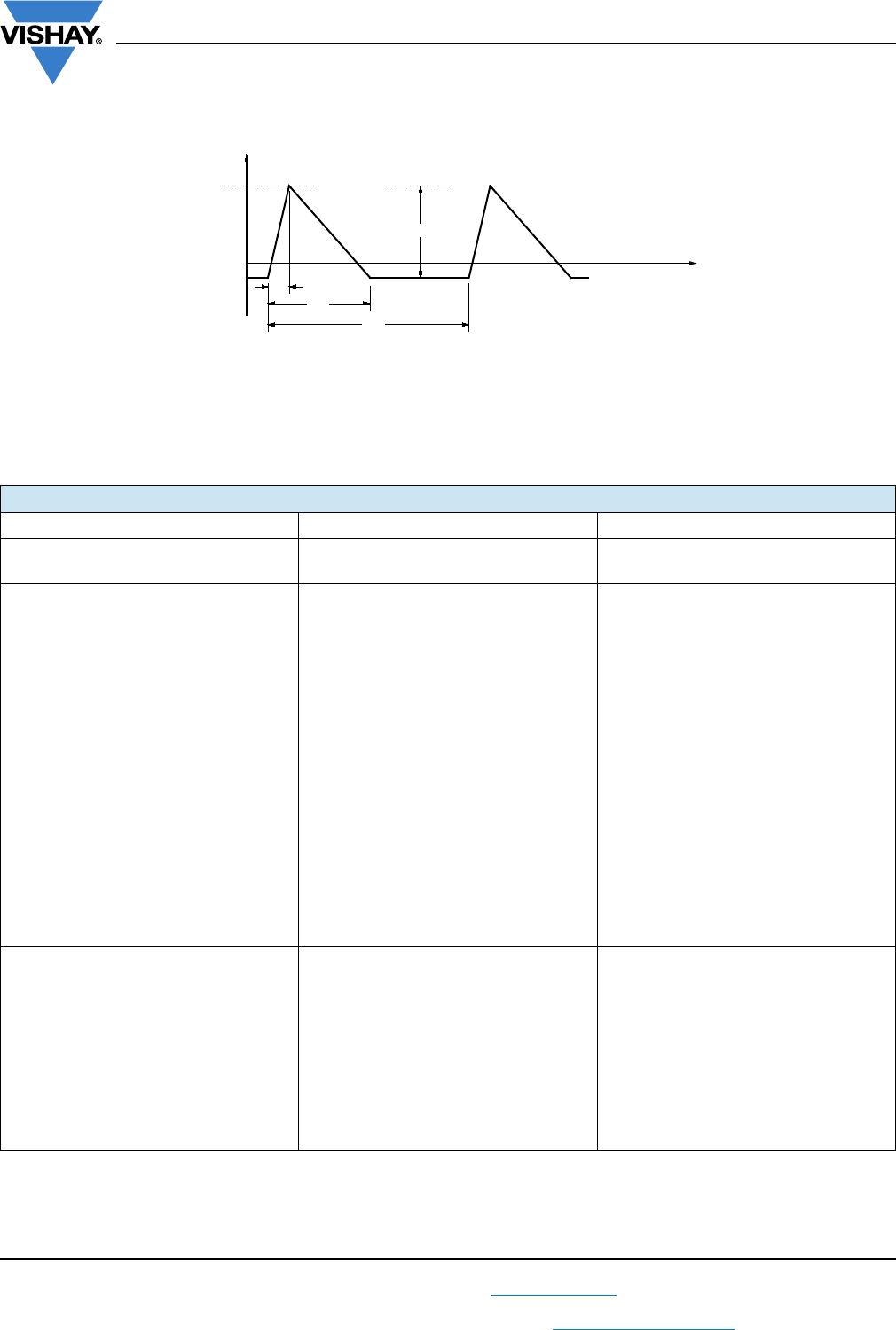
EXAMPLE
C = 4n7 - 1600 V used for the voltage signal shown in next drawing.
U
p-p
= 1000 V; U
p
= 900 V; T
1
= 12 µs; T
2
= 64 µs; T
3
= 4 µs
The ambient temperature is 80 °C. In case of failure, the oscillation is blocked.
Checking conditions:
1. The peak voltage U
p
= 900 V is lower than 1600 V
DC
2. The peak-to-peak voltage 1000 V is lower than 22 x 550 V
AC
= 1600 U
p-p
3. The voltage pulse slope (dU/dt) = 1000 V/4 µs = 250 V/µs. This is lower than 8000 V/µs (see specific reference data for each
version).
4. The dissipated power is 35 mW as calculated with fourier terms and typical tgd.
The temperature rise for w
max.
= 6.0 mm and pitch = 15 mm will be 35 mW / 11 mW/°C = 3.2 °C
This is lower than 10 °C temperature rise at 80 °C, according graph.
5. Oscillation is blocked
6. Not applicable
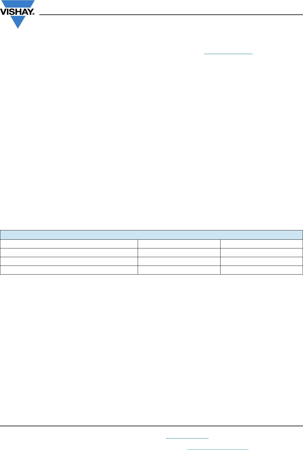
VOLTAGE CONDITIONS FOR 6 ABOVE
ALLOWED VOLTAGES T
amb
85 °C 85 °C < T
amb
105 °C
Maximum continuous RMS voltage U
RAC
U
RAC
Maximum temperature RMS-over voltage (< 24 h) 1.25 x U
RAC
1.25 x U
RAC
Maximum peak voltage (V
o-p
) (< 2 s) 1.6 x U
RDC
1.1 x U
RDC
MMKP383
www.vishay.com
Vishay BCcomponents
Revision: 15-Jan-15
12
Document Number: 28173
For technical questions, contact: dc-film@vishay.com
THIS DOCUMENT IS SUBJECT TO CHANGE WITHOUT NOTICE. THE PRODUCTS DESCRIBED HEREIN AND THIS DOCUMENT
ARE SUBJECT TO SPECIFIC DISCLAIMERS, SET FORTH AT www.vishay.com/doc?91000
VOLTAGE SIGNAL
INSPECTION REQUIREMENTS
General Notes
Sub-clause numbers of tests and performance requirements refer to the “Sectional Specification, Publication IEC 60384-17 and
Specific Reference Data”.
Voltage
U
p
T
3
T
1
T
2
U
p-p
Time
GROUP C INSPECTION REQUIREMENTS
SUB-CLAUSE NUMBER AND TEST CONDITIONS PERFORMANCE REQUIREMENTS
SUB-GROUP C1A PART OF SAMPLE
OF SUB-GROUP C1
4.1 Dimensions (detail) As specified in chapters “General Data” of
this specification
4.3.1 Initial measurements Capacitance
Tangent of loss angle:
for C 1 µF at 100 kHz or
for C > 1 µF at 10 kHz
4.3 Robustness of terminations Tensile: load 10 N; 10 s
Bending: load 5 N; 4 x 90°
No visible damage
4.4 Resistance to soldering heat Method: 1A
Solder bath: 280 °C ± 5 °C
Duration: 10 s
4.14 Component solvent resistance Isopropylalcohol at room temperature
Method: 2
Immersion time: 5 min ± 0.5 min
Recovery time: min. 1 h, max. 2 h
4.4.2 Final measurements Visual examination No visible damage
Legible marking
Capacitance |C/C| 1 % of the value measured initially
Tangent of loss angle Increase of tan :
0.0005 for: C 100 nF or
0.001 for: 100 nF < C 470 nF or
0.0015 for: C > 470 nF
Compared to values measured in 4.3.1

MKP383411063JC02Z0

Mfr. #:
Manufacturer:
Vishay
Description:
Capacitor, Film, MKP, 630Vdc, 220Vac, 0, 11F, 7, 5pitch
Lifecycle:
New from this manufacturer.
Delivery:
DHL FedEx Ups TNT EMS
Payment:
T/T Paypal Visa MoneyGram Western Union